Touch sensor, touch pad and input device

a touch sensor and input device technology, applied in the field of touch sensors, can solve the problems of not being easy to discriminate, and not being able to additionally detect a depression in the z-direction

Inactive Publication Date: 2010-11-02
SANYO ELECTRIC CO LTD
View PDF10 Cites 106 Cited by
  • Summary
  • Abstract
  • Description
  • Claims
  • Application Information

AI Technical Summary

Problems solved by technology

However, even though the conventional touch pad can detect a movement in the x-y plane, it cannot additionally detect a depression in the z-direction.
Hence, it has not been easy to discriminate, for example, between dragging and moving a cursor.

Method used


Image

  • Touch sensor, touch pad and input device
  • Touch sensor, touch pad and input device
  • Touch sensor, touch pad and input device

Examples


Embodiment Construction

[0032]Next, an embodiment of the present invention is described with reference to the drawings. In the following description and drawings, the same or similar components are designated by the same or similar reference numerals. It should be noted that the drawings are schematic. Accordingly, sizes, ratios and the like are different from actual ones. For this reason, specific dimensions and the like should be determined in consideration of the following description. In addition, some of the sizes or ratios are different among the drawings.

(Touch Sensor)

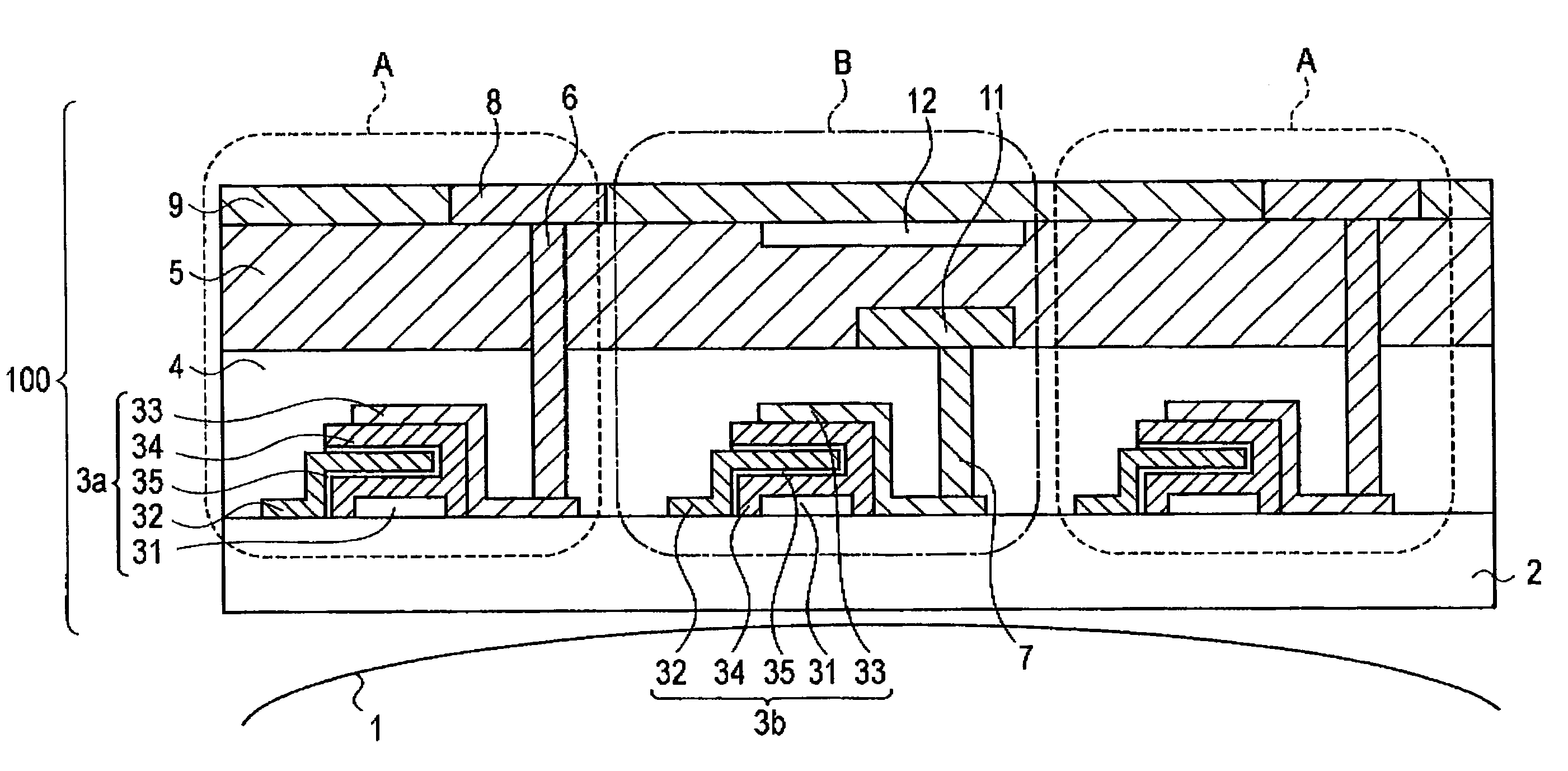
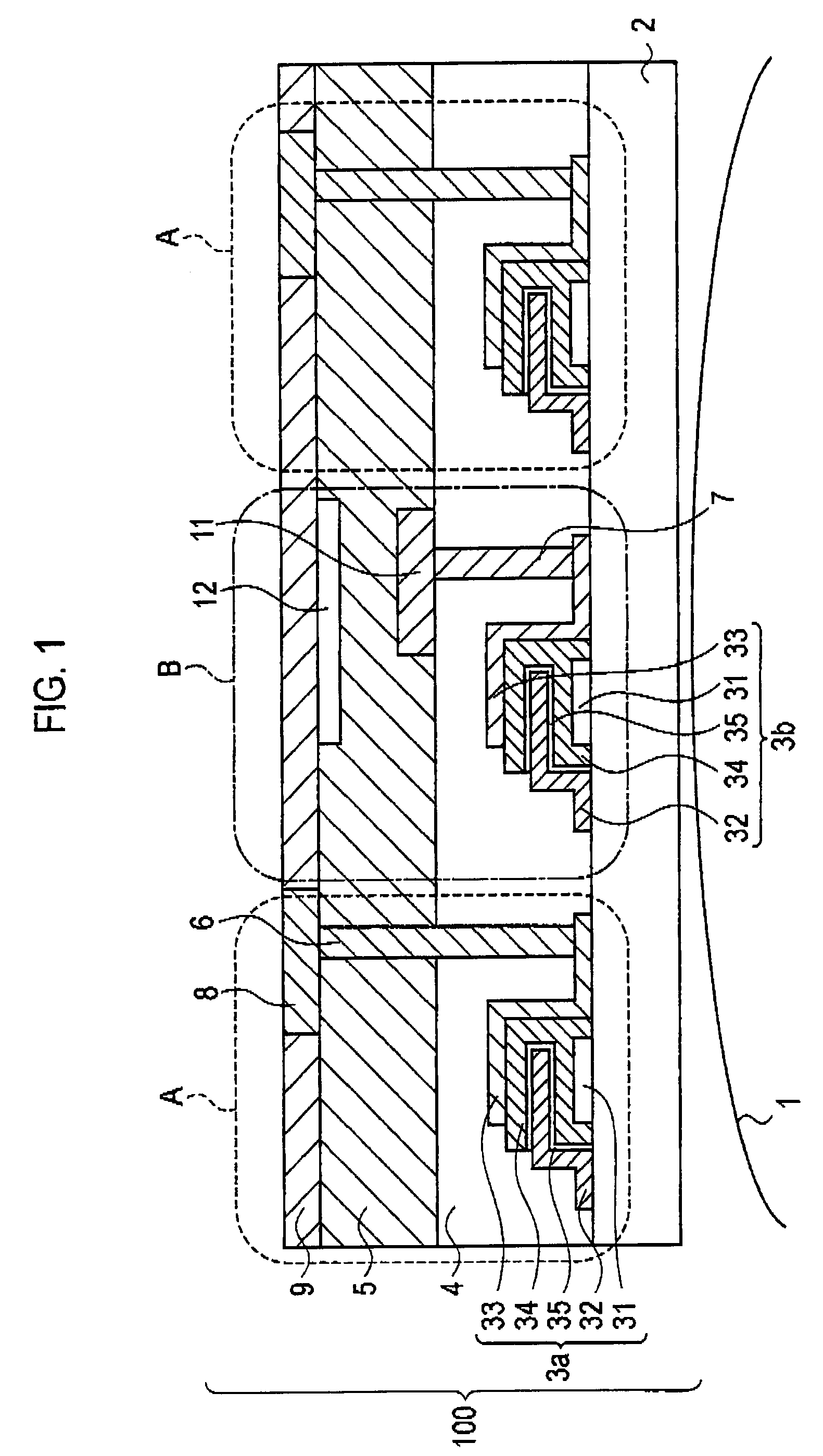
[0033]A touch sensor 100 of the present invention includes contact sensors A and pressure sensors B, as shown in FIG. 1. Each of the contact sensors A detects a change in electric potential when an object contacts a surface. Each of the pressure sensors B detects a change in a pressure when an object depresses a surface. Here, the “object” indicates, for example, a part of a human body such as a finger or a hand, or an apparatus such a...


PUM


Abstract

A touch sensor includes a contact sensor and a pressure sensor. The contact sensor includes a first electrode and a first switching element connected to the first electrode, and detects a change in an electric potential when an object contacts a surface. The pressure sensor includes a second electrode and a second switching element connected to the second electrode, and detects a change in a pressure when an object depresses the surface. The touch sensor includes a plurality of the contact sensors and a plurality of the pressure sensors disposed regularly in an array.

Description

CROSS REFERENCE TO RELATED APPLICATIONS[0001]This application is based upon and claims the benefit of priority from prior Japanese Patent Application No.2006-086704, filed on Mar. 27, 2006; the entire contents of which are incorporated herein by reference.BACKGROUND OF THE INVENTION[0002]1. Field of the Invention[0003]The present invention relates to a touch sensor, a touch pad and an input device.[0004]2. Description of the Related Art[0005]Conventionally, a touch pad, which detects the position of the touched surface and displays the position on a display when touched by the surface, has been known in general. As such a touch pad, there are two major types; a capacitance type used for a touch pad of a personal computer or the like, and a pressure sensitive type used in a gaming machine, a personal digital assistant (PDA) or the like (e.g., refer to Japanese Patent Publication No. 2003-196007).[0006]In addition, a technique of a touch pad, which enables easy character input even wh...

Claims


Application Information

Patent Timeline
Patent Type & Authority Patents(United States)
IPC IPC(8): G06F3/041G06F3/045G06F3/033G06F3/0354G06F3/038
CPCG06F3/041G06F3/04144G06F3/047G06F2203/04106
Inventor SANO, TAKESHIKURAMOTO, KEIICHIFUJII, HIROYUKIWAKISAKA, KENICHIRO
Owner SANYO ELECTRIC CO LTD
Why Eureka
Try Eureka