Method for manufacturing a ceramic multi-layered substrate

a multi-layered substrate and ceramic technology, applied in the field of ceramic multi-layered substrate manufacturing, can solve the problems of large-scale cosub>2 /sub>laser irradiation apparatus, high cost, and failure of press-bonded sheets, etc., to achieve accurate and easy manufacturing of ceramic multi-layered substrates.

Inactive Publication Date: 2010-11-16
MURATA MFG CO LTD
View PDF19 Cites 16 Cited by
  • Summary
  • Abstract
  • Description
  • Claims
  • Application Information

AI Technical Summary

Benefits of technology

[0013]To overcome the problems described above, preferred embodiments of the present invention provide a source substrate for forming ceramic multi-layered substrates and a method for accurately and easily manufacturing a ceramic multi-layered substrate.

Problems solved by technology

In Japanese Unexamined Utility Model Registration Application Publication No. 4-38071, however, an expensive, large-scale CO2 laser irradiation apparatus is required.
The laser irradiation requires a long time.
In the method disclosed in Japanese Unexamined Patent Application Publication No. 5-75262, failures, such as deformation and breakage, may occur in the press-bonded sheets during conveyance due to the dividing grooves.
When the heat-treated substrate is bent, the substrate may be broken at undesired locations other than the grooves, which results in defective articles.
Although the substrate is separated along the dividing grooves, sections may have irregular shapes, which results in out-of-specification products.
In the method disclosed in Japanese Unexamined Patent Application Publication No. 2001-332857, the cavities may collapse or be deformed due to the uneven thickness of the ceramic green sheets and uneven pressing force.
Thus, it is difficult to accurately form cavities.
In the method disclosed in Japanese Unexamined Patent Application Publication No. 2005-311225, it is necessary to prepare the ceramic green sheets into which the removable material is charged such that the sheets have a shape corresponding to the outside shape of the laminated electronic component, which results in a complicated production process.

Method used


Image

  • Method for manufacturing a ceramic multi-layered substrate
  • Method for manufacturing a ceramic multi-layered substrate
  • Method for manufacturing a ceramic multi-layered substrate

Examples


first preferred embodiment

[0066]A method for manufacturing a ceramic multi-layered substrate according to a first preferred embodiment will be described below with reference to FIGS. 1 to 9.

[0067]A brief outline of the method for manufacturing a ceramic multi-layered substrate will be described below.

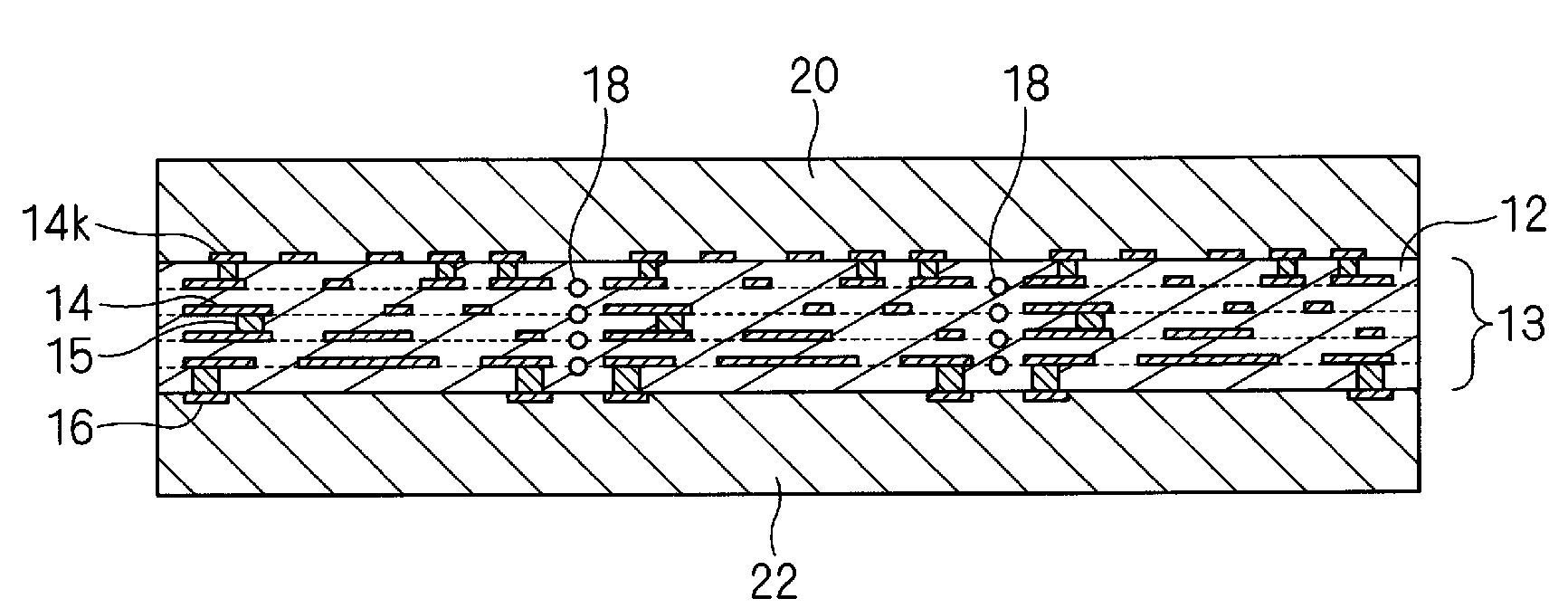
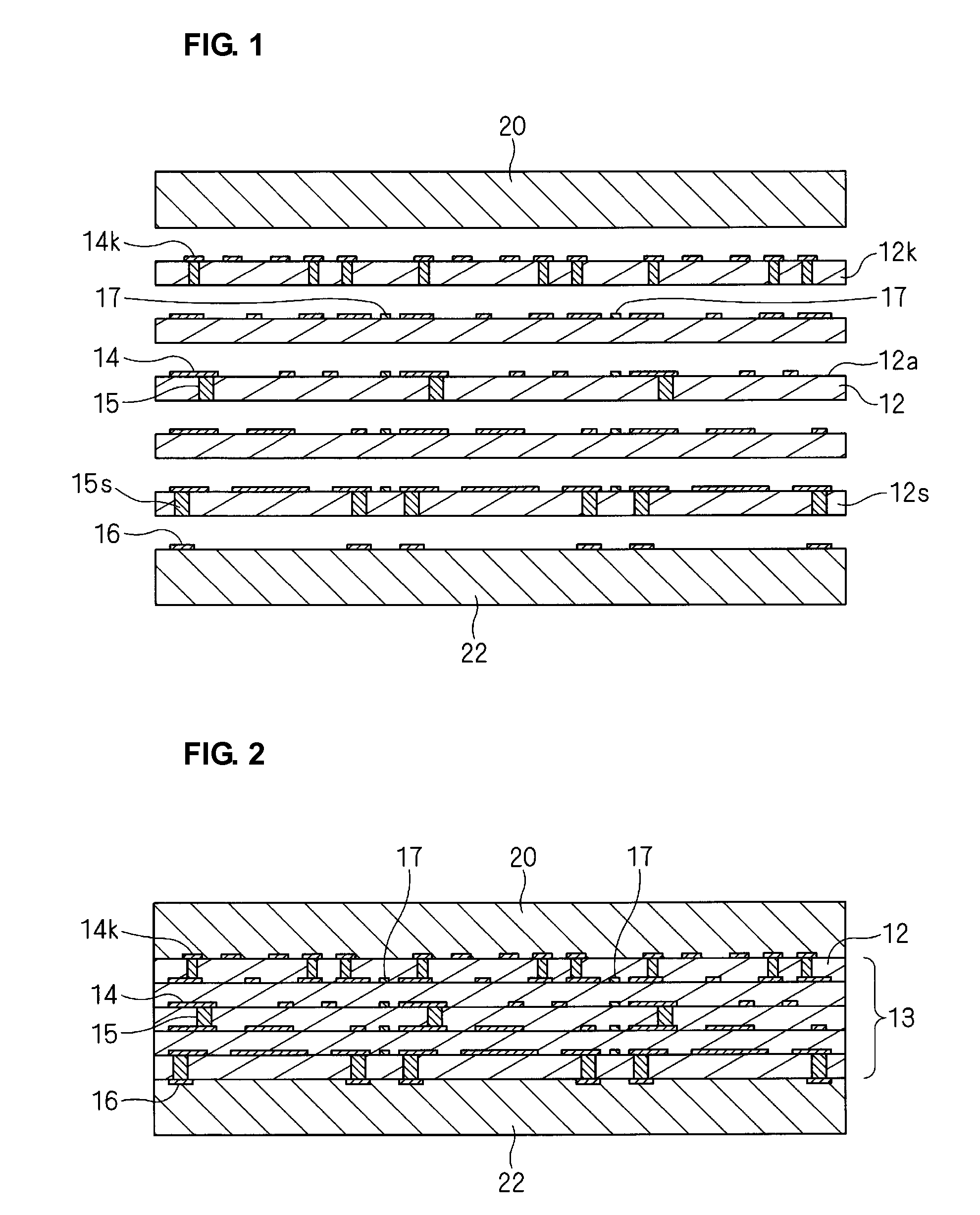
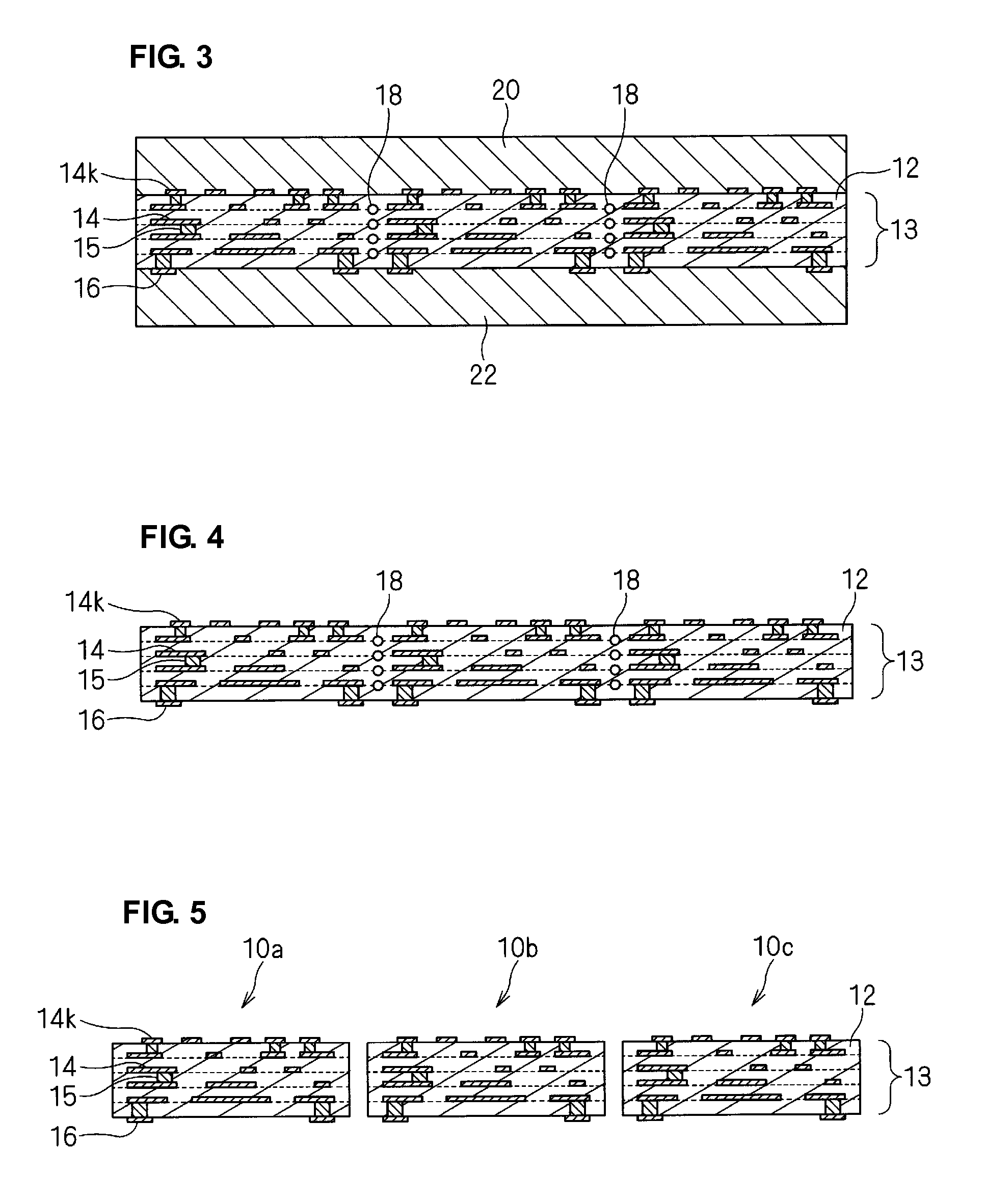
[0068]As shown in FIG. 1, a plurality of ceramic green sheets 12 and shrinkage inhibiting green sheets 20 and 22 are prepared and stacked in a predetermined order to form a composite laminate in which the shrinkage inhibiting green sheets 20 and 22 are in close contact with both surfaces of a green ceramic laminate 12, as shown in FIG. 2.

[0069]A green ceramic laminate 13 includes a portion to be formed into a plurality of ceramic multi-layered substrates. The green ceramic laminate 13 includes in-plane conductive patterns 14 to be formed into internal electrodes, internal leads, embedded elements, and other electrical elements in the ceramic multi-layered substrates, and separation patterns 17 arranged along bou...

second preferred embodiment

[0107]A method for manufacturing a ceramic multi-layered substrate according to a second preferred embodiment will be described below with reference to FIGS. 13 to 18. The method for manufacturing a ceramic multi-layered substrate according to the second preferred embodiment is substantially the same as in the first preferred embodiment. Points of difference from the first preferred embodiment will be described below. The same elements as those in the first preferred embodiment are designated using the same reference numerals, and descriptions thereof are omitted.

[0108]In the second preferred embodiment, ceramic multi-layered substrates are produced by the same method as that in the first preferred embodiment, except that separation patterns 17x which are formed between the ceramic green sheets 12 and arranged along boundaries (separation lines) between the ceramic multi-layered substrates are composed of a special material.

[0109]As shown in FIG. 13, the plurality of ceramic green s...


PUM

PropertyMeasurementUnit
shrinkageaaaaaaaaaa
softening pointaaaaaaaaaa
viscosityaaaaaaaaaa

Abstract

A method for manufacturing a ceramic multi-layered substrate includes a first step of forming a green ceramic laminate including a plurality of stacked green ceramic base layers, a second step of firing the green ceramic laminate to sinter the green ceramic layers, and a third step of separating the sintered ceramic laminate formed by firing the green ceramic laminate into a ceramic multi-layered substrate. The green ceramic base layers stacked in the first step include a separation pattern formed along separation lines, the separation pattern disappearing during firing. In the third step, the sintered ceramic laminate is separated into a plurality of ceramic multi-layered substrates separated through a cavity formed by the disappearance of the separation pattern during the firing in the second step.

Description

BACKGROUND OF THE INVENTION[0001]1. Field of the Invention[0002]The present invention relates to a method for manufacturing a ceramic multi-layered substrate. In particular, the present invention relates to a method for manufacturing a ceramic multi-layered substrate including a plurality of stacked ceramic layers.[0003]2. Description of the Related Art[0004]Ceramic multi-layered substrates including a plurality of stacked ceramic layers can be efficiently produced by simultaneously firing a source substrate including a plurality of ceramic multi-layered substrates and cutting the source substrate into individual ceramic multi-layered substrates after firing.[0005]For example, Japanese Unexamined Utility Model Registration Application Publication No. 4-38071 discloses that ceramic green sheets having dividing lines are transferred and laminated to form a laminate, dividing grooves are formed by, for example, irradiating the dividing lines with a CO2 laser after the laminate is subje...

Claims


Application Information

Patent Timeline
Patent Type & Authority Patents(United States)
IPC IPC(8): C03B29/00
CPCH05K3/0052H05K1/0272H05K1/0306H05K3/4611H05K3/4629H05K2203/302H05K2203/308H05K3/46
Inventor KAWAMURA, AKIYOSHITSUKIZAWA, TAKAYUKIIKEDA, TETSUYACHIKAGAWA, OSAMU
Owner MURATA MFG CO LTD
Why Eureka
Try Eureka