
Hollow rack bar and method of manufacturing the hollow rack bar

a technology of hollow racks and racks, applied in the field of hollow racks, to achieve the effect of easy and accurate manufacturing

Inactive Publication Date: 2020-02-06
NETUREN CO LTD
View PDF0 Cites 0 Cited by
  • Summary
  • Abstract
  • Description
  • Claims
  • Application Information

AI Technical Summary

Benefits of technology

The present invention provides a method for easily and accurately manufacturing hollow rack bars that have a rack portion engaged with a pinion gear and are supported by a yoke. The invention also provides a hollow rack bar with such a rack portion and supported faces.

Problems solved by technology

In the case of solid rack bar, since it is difficult to manufacture a variable rack by machining, wherein the rack tooth pitch and the shape change along the axial direction, the variable rack is made by forging.

Method used


Image

  • Hollow rack bar and method of manufacturing the hollow rack bar
  • Hollow rack bar and method of manufacturing the hollow rack bar
  • Hollow rack bar and method of manufacturing the hollow rack bar

Examples


embodiment 1

[0050]A hollow rack bar according to the embodiment is used for a power steering system for automobiles.

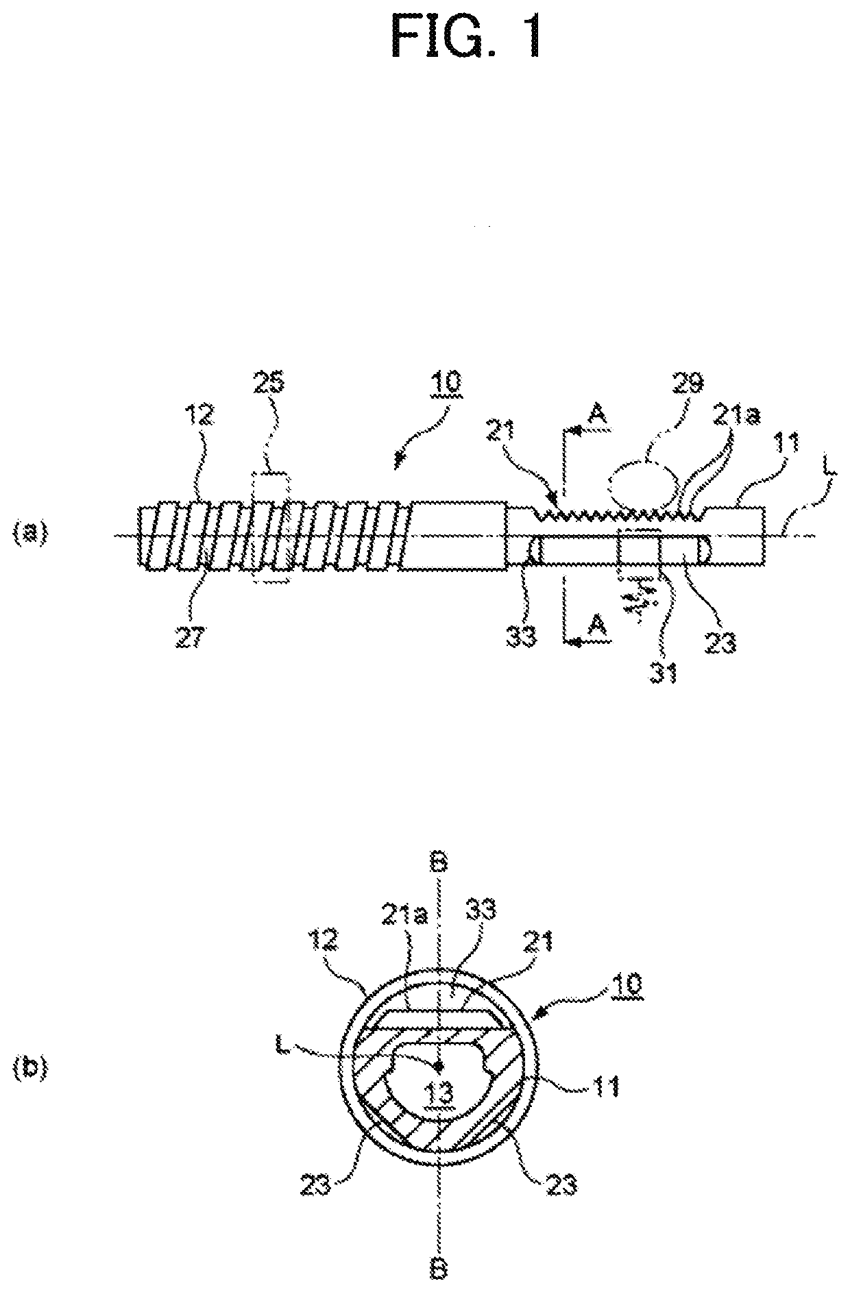
[0051]FIG. 1 shows a hollow rack bar according to a first embodiment of the present invention, wherein (a) is a side view, and (b) is a cross-sectional view taken along A-A in (a).

[0052]As shown in FIG. 1, the hollow rack bar 10 includes a small-diameter portion 11, its outermost cross-section being in a mostly circular shape, and a large-diameter portion 12, its outermost cross-section being larger than that of the small-diameter portion 11 and in a mostly circular shape. The small-diameter portion 11 and the large-diameter portion 12 are provided at different positions in a direction along an axis L.

[0053]The small-diameter portion 11 includes a rack portion 21 formed on a part of its outer face, and supported faces 23 formed on its outer face opposite to the rack teeth portion 21. In the portion of the small-diameter portion 11 where the rack portion 21 and the supported faces ...

embodiment 2

[0091]A second embodiment will hereinafter be described.

[0092]In the first embodiment, the supported faces 23 are formed by performing removal processing such as cutting and grinding. In the second embodiment, the hollow rack bar 10 is manufactured in the same method as the first embodiment except that the supported faces 23 are formed by deformation processing such as pressing.

[0093]FIG. 6 shows the process of forming the supported faces 23 by the manufacturing method in the second embodiment.

[0094]In this process, the rack portion 21 is formed in the circular tube material in the same method as the first embodiment, and then the rack portion 21 is maintained and fastened to a fastening mold 46 having a rack fixture 45.

[0095]By using a movable mold 48 having a V-shaped pressurizing face 47 formed in an angle corresponding to a pair of supported faces 23 to be formed, the arc-shaped outer face is pressurized and deformed on the back side of the teeth of the rack portion 21 to form t...


PUM


Abstract

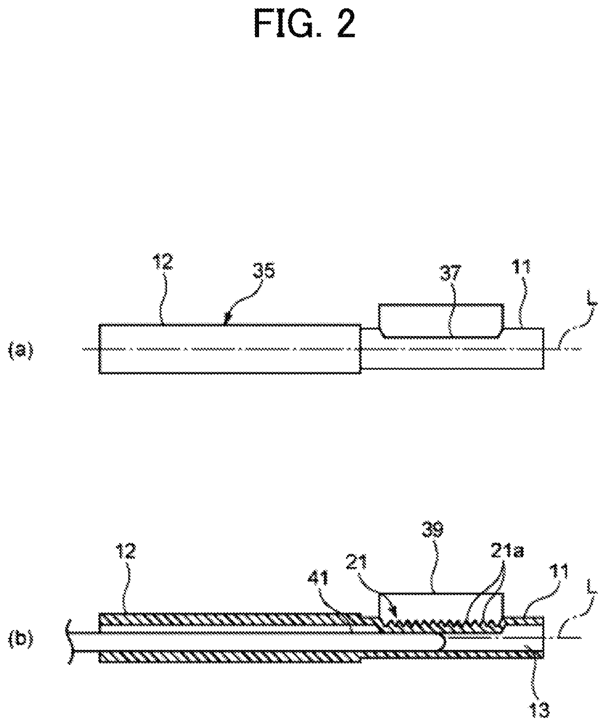
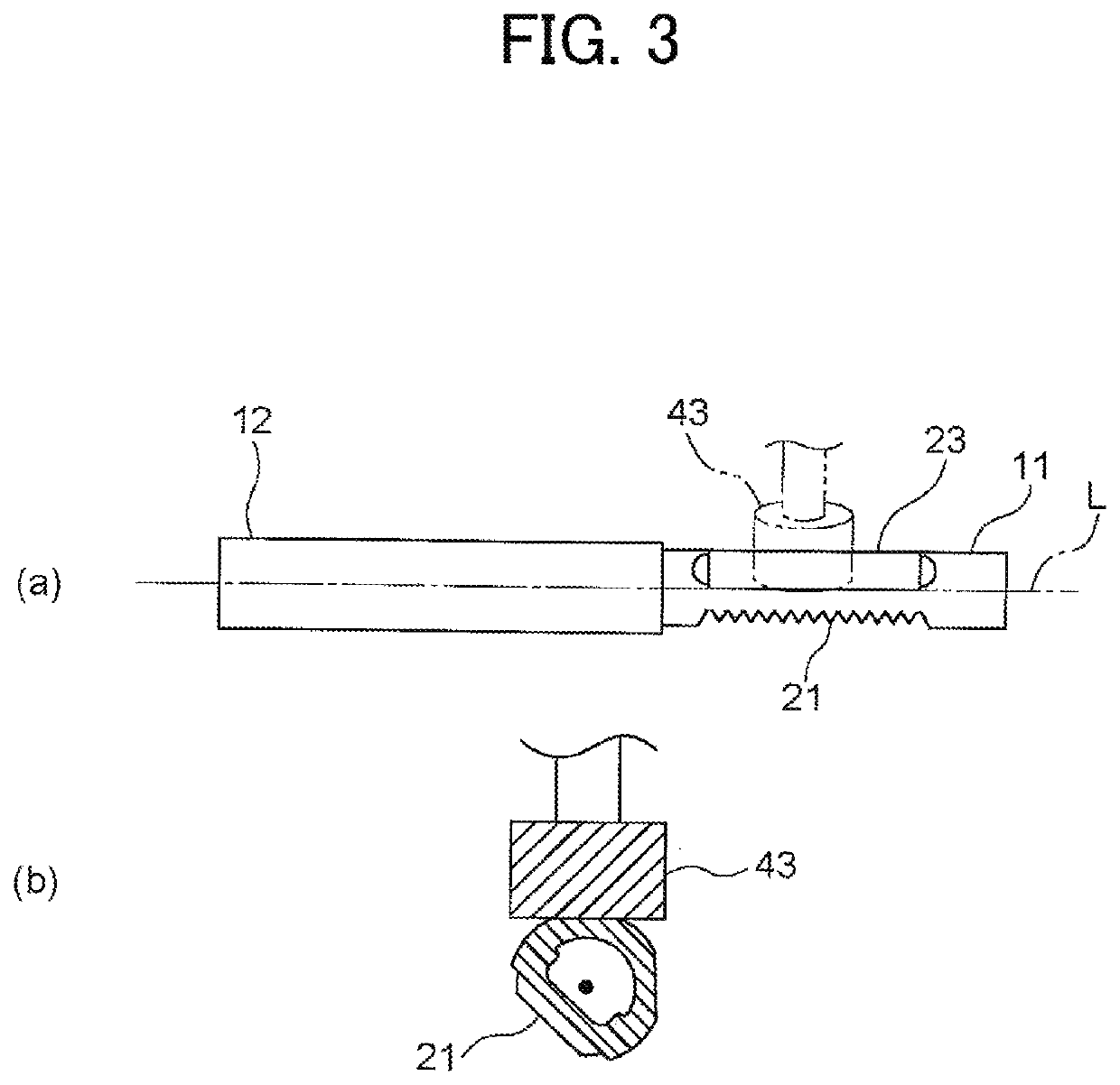
Provided is a hollow rack bar including a rack portion that is engaged with a pinion gear and faces supported by a yoke. The hollow rack bar includes: the rack portion engaged with the pinion gear; and the supported faces provided on a back side of teeth of the rack portion and supported by the yoke. The rack portion is formed by locating a toothed mold on an outer face of a circular tube material, and inserting a cored bar into the circular tube material to pressurize an inner face, thereby transferring a shape of the toothed mold. The supported faces are formed by removal processing or deformation processing of a back side of the teeth rack portion of the circular tube material.

Description

CROSS-REFERENCE TO RELATED APPLICATION[0001]This application is a Divisional of copending U.S. application Ser. No. 15 / 329,738, filed on Jan. 27, 2017, which is a 371 of International Application No. PCT / JP2015 / 003792, filed on Jul. 28, 2015, which claims the benefit of priority from prior Japanese Patent Application No. 2014-153372, filed on Jul. 28, 2014, the entire contents of all of which are incorporated herein by references.TECHNICAL FIELD[0002]The present invention relates to a hollow rack bar used for automobile power steering systems and a method of manufacturing the same.BACKGROUND ART[0003]Automobile power steering systems include the one wherein a concave or convex supported faces are provided on the back side of the rack teeth of a rack bar, and by pushing down on the supported faces with a yoke to support the back side of the rack bar, a pinion gear and the rack are made to be in well-engaged state (Patent Literature 1).[0004]A solid rack bar is used for ordinary power...

Claims


Application Information

Patent Timeline
Patent Type & Authority Applications(United States)
IPC IPC(8): B62D3/12B21K1/76B62D5/04F16H25/22F16H55/26
CPCB62D3/126F16H55/26B62D5/0421B62D5/0448F16H25/2204B21K1/768B21J5/12C21D1/18
Inventor KATO, TAKASHIYAMAWAKI, TAKASHI
Owner NETUREN CO LTD
Learn More