Method of sequentially actuating power supply switches including a neutrally connected switch

a power supply switch and neutral connection technology, applied in the direction of contact engagements, electrical devices, contacts, etc., can solve the problems of increasing the delay or lag time between actual connection of electrical contacts at each of the switched poles, undesirable known system configurations, and inconvenience for users, so as to achieve the effect of convenient installation

Active Publication Date: 2010-11-16
RELIANCE CONTROLS
View PDF19 Cites 11 Cited by
  • Summary
  • Abstract
  • Description
  • Claims
  • Application Information

AI Technical Summary

Benefits of technology

[0013]It is an object of the present invention to provide an interlock assembly that can be readily installed to provide a single operating mechanism to control switching between the supply of electrical power from a first (typically utility) power supply and / or a second (typically generator) power supply at a load center. In addition, it is an object of the present invention to provide an interlock assembly configured to make and / or break (e.g., regulate interruption) of each neutral line connection at the load center in a sequenced manner. It is another object of the present invention to provide an interlock assembly configured to provide control of switching between the supply of electrical power from utility service and from a generator in such a manner that connection of each respective neutral conductor is made before electrical connection of the respective “hot” conductors is made. In this manner, the interlock assembly prevents the “hot” conductors of the utility service or generator from being connected to the service bus conductor of the load center without the associated respective neutral line conductor having been first connected to the neutral bus conductor of the building in advance. Yet another object of the present invention is to provide an interlock assembly configured to interrupt connection of each neutral conductor of the generator or utility service after the connection of the associated “hot” conductors is interrupted, while assuring that the utility service and the generator do not simultaneously feed electrical power to each other or the service bus conductor of the load center. A still further object of the present invention is to provide an interlock assembly configured to ensure that connection of the neutral conductor of the utility service or generator cannot be interrupted without previous interruption of the connection of the respective “hot” conductors. Still another object of the present invention is to provide a means for linking or tying switch members of a number of switches together in a manner that results in simultaneous or sequential movement of the switch members between positions.

Problems solved by technology

However, this configuration has drawbacks when used with bonded-neutral generators.
It is this undesired dual path for electrical current to follow back from the electrical load to the generator that creates a problem.
Thus, known system configurations are undesirable because such configurations allow a normal flow of electrically current to pass via the neutral conductor of the building to the safety ground conductor of the generator.
Another drawback of above-described system configurations is that the flow of electrical current to the safety ground conductor of the generator is known to trigger a ground fault circuit interrupt at the generator.
However, this known system configuration also has drawbacks, specifically involving the switching sequence of the neutral transfer switch assembly that controls the electrical connection of the neutral conductor of the utility service or generator with the neutral bus conductor of the building.
Given that each of the operating handles (i.e., the handle interconnecting the switch for each “hot” conductor connection, and the handle for operating the neutral switch for the neutral connection) of the transfer switch are mechanically connected together, this system configuration can increase the delay or lag time between actual connection of the electrical contacts at each of the switched poles.
This series connection of electrical loads results in the same electrical current draw through each electrical load, causing much larger voltages to be experienced by the electrical loads.
Under certain conditions, this can be the equivalent to plugging a standard 120-volt appliance into a 240-volt outlet, causing an undesirable over-voltage condition at the load.
However, the drawback of this system configuration is that the electrical connection of the neutral conductor of the generator with the neutral conductor of the utility service results in the flow of electrical current through the generator safety ground, which is undesired for reasons described above.

Method used


Image

  • Method of sequentially actuating power supply switches including a neutrally connected switch
  • Method of sequentially actuating power supply switches including a neutrally connected switch
  • Method of sequentially actuating power supply switches including a neutrally connected switch

Examples


Embodiment Construction

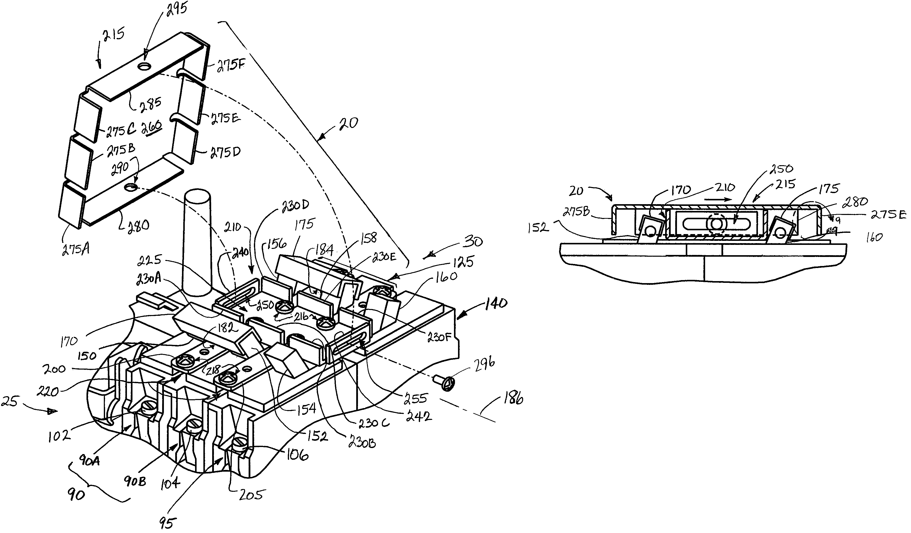
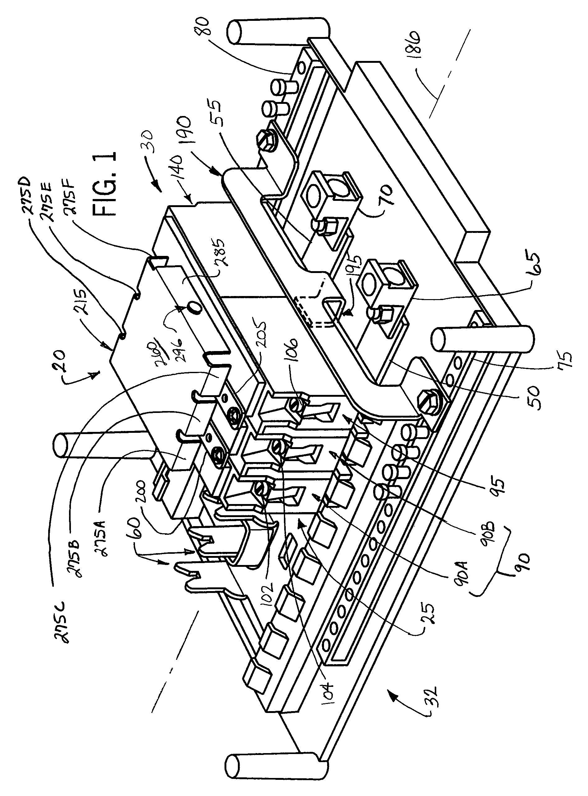
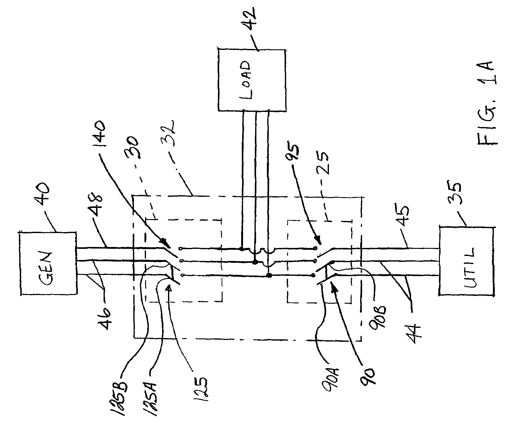
[0072]FIG. 1 illustrates one embodiment of an interlock assembly 20 for a pair of opposed multiple switch assemblies 25 and 30 in accordance with the present invention. The pair of opposed multiple switch assemblies 25 and 30 are electrically connected at a load center or electrical panel 32 of a building (e.g., hospital, residential unit, factory etc.). FIG. 1A is a circuit diagram that illustrates the electrical connection to the electrical panel 32 in a manner generally configured to switch the supply of electrical power between a utility service 35 and a generator 40 to an electrical load 42. The utility service 35 generally includes a pair of “hot” line conductors 44 and a neutral conductor 45 electrically connected to the electrical panel 32. In a similar manner, the generator source 40 includes a pair of “hot” line conductors 46 and a neutral conductor 48 electrically connected to the electrical panel 32.

1. Electrical Panel

[0073]Referring back to FIG. 1, the preferred electri...


PUM


Abstract

An interlock assembly for use with a pair of aligned multiple switch assemblies configured to control the supply of electrical power to an electrical panel. Each multiple switch assembly includes a two-pole transfer switch for a pair of “hot” conductors, and a single-pole transfer switch for a neutral connection. The interlock assembly is movably mounted relative to both of the multiple switch assemblies, and is configured to control a sequence of connection and interruption of each neutral connection relative to switching the hot conductors associated with switching each multiple switch assembly. The interlock assembly prevents the “hot” conductors of each multiple switch assembly from being connected without the associated respective neutral connection having been made in advance. The interlock assembly also ensures that the neutral connection of each multiple switch assembly is interrupted without previous interruption of the connection of the respective “hot” conductors.

Description

CROSS-REFERENCE TO RELATED APPLICATION[0001]This application is a divisional of application Ser. No. 11 / 370,789 filed Apr. 14, 2006 now U.S. Pat. No. 7,462,791.FIELD OF THE INVENTION[0002]This invention relates to an interlock assembly for a load center, and more particularly to an interlock assembly that is configured to interrupt a neutral connection in a desired sequential manner during the process of transferring an electrical connection between a utility service and a generator.BACKGROUND OF THE INVENTION[0003]In today's electrical supply systems, there are occasions when alternate sources of electrical power are necessary or desirable. For example, the capability of switching from utility power to emergency generator power is extremely important for many businesses, hospitals and industries, as well as residential dwellings.[0004]In certain applications, it is desirable for separate electrical circuits or even separate groups of electrical circuits to be arranged so that when ...

Claims


Application Information

Patent Timeline
Patent Type & Authority Patents(United States)
IPC IPC(8): H01H9/20
CPCH01H9/26H01H2300/018
Inventor FLEGEL, DAVID D.
Owner RELIANCE CONTROLS
Why Eureka
Try Eureka