Lighting devices and methods of installing light engine housings and/or trim elements in lighting device housings

a technology of lighting device housing and engine housing, which is applied in the field of lighting devices, can solve the problems of incandescent light bulbs that are very energy-inefficient light sources, incandescent light bulbs have relatively short lifetimes, and incandescent light bulbs are relatively short life periods, so as to achieve convenient use

Active Publication Date: 2008-05-08
IDEAL IND LIGHTING LLC
View PDF10 Cites 326 Cited by
  • Summary
  • Abstract
  • Description
  • Claims
  • Application Information

AI Technical Summary

Benefits of technology

[0008] In accordance with one aspect of the present inventive subject matter, it would be desirable to provide structure which retains a light engine and / or a trim assembly within any of a variety of recessed downlight housings (or, for that matter, any lighting device housings), and to be able, in such structure, to accommodate any of a variety of housings available from a variety of sources, such housings having a variety of housing diameters (and other dimensions), a variety of obstructions, etc. (and some of which include Edison sockets rigidly attached to moveable bases, while others have sockets that are loosely attached inside the housing and are provided mechanical attachment on the trim). It would be desirable to provide devices which could accommodate a wide range of housing diameters and which could work with loosely or rigidly mounted sockets. Further, it would be desirable to provide such features with structure that would be simple, easy to use and inexpensive.
[0009] In accordance with another aspect of the present inventive subject matter, it would be desirable to provide structure which would reduce or eliminate the tendency for trim sagging—that is, it was recognized that so-called “trim” elements of many conventional devices have a tendency to sag to a slight degree (i.e., it is common for trim elements to sag 1 / 16″ to ¼″ when installed with friction clips).
[0010] In accordance with the present inventive subject matter, there is provided a clip which is rotated (as discussed herein in more detail) to decrease resistance while sliding the light engine and / or trim into a housing, and which locks into place when twisted.
[0011] In some embodiments of the present inventive subject matter, described in more detail herein, there is provided a spring-steel retention clip which is mounted to the top of the trim or the light engine housing and which rotates for ideal function for shipment, sliding into the housing, locking into position, or removal. In some such embodiments, the clips may be rotated so that they are inside the outer diameter of the trim or the light engine housing to minimize likelihood of damage during shipment. Such embodiments allow the assembly to be easily installed in housings with fixed Edison sockets. In some such embodiments:
[0013] the angle with respect to a perpendicular from the tangent to the edge of the trim should be sufficient to allow the clip to contact the housing as it is being pushed into the housing with minimal resistance;
[0015] in this fully-deployed condition, the clips are perpendicular to the tangent of the trim and the ends of the clips dig into the housing and apply additional upward force to the trim, eliminating the chance for the trim and / or light engine sagging;

Problems solved by technology

It is well-known that incandescent light bulbs are very energy-inefficient light sources—about ninety percent of the electricity they consume is released as heat rather than light.
Fluorescent light bulbs are more efficient than incandescent light bulbs (by a factor of about 10) but are still less efficient than solid state light emitters, such as light emitting diodes.
In addition, as compared to the normal lifetimes of solid state light emitters, e.g., light emitting diodes, incandescent light bulbs have relatively short lifetimes, i.e., typically about 750-1000 hours.
Fluorescent bulbs have longer lifetimes (e.g., 10,000-20,000 hours) than incandescent lights, but provide less favorable color reproduction.
Another issue faced by conventional light fixtures is the need to periodically replace the lighting devices (e.g., light bulbs, etc.).
Such issues are particularly pronounced where access is difficult (e.g., vaulted ceilings, bridges, high buildings, traffic tunnels) and / or where change-out costs are extremely high.
Light-producing device lifetime is typically much shorter, thus creating the need for periodic change-outs.

Method used


Image

  • Lighting devices and methods of installing light engine housings and/or trim elements in lighting device housings
  • Lighting devices and methods of installing light engine housings and/or trim elements in lighting device housings
  • Lighting devices and methods of installing light engine housings and/or trim elements in lighting device housings

Examples


first embodiment

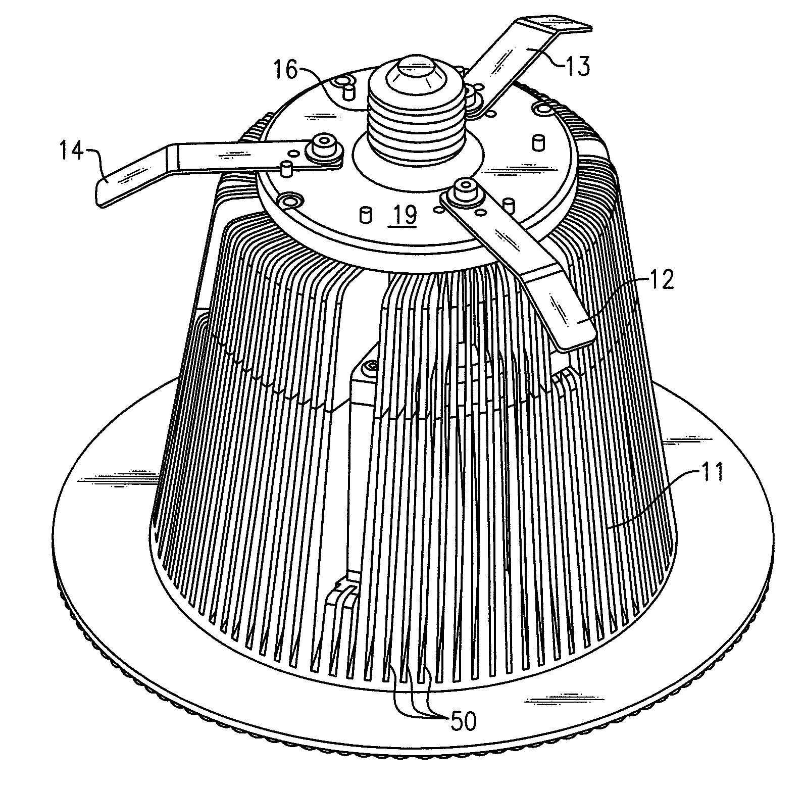
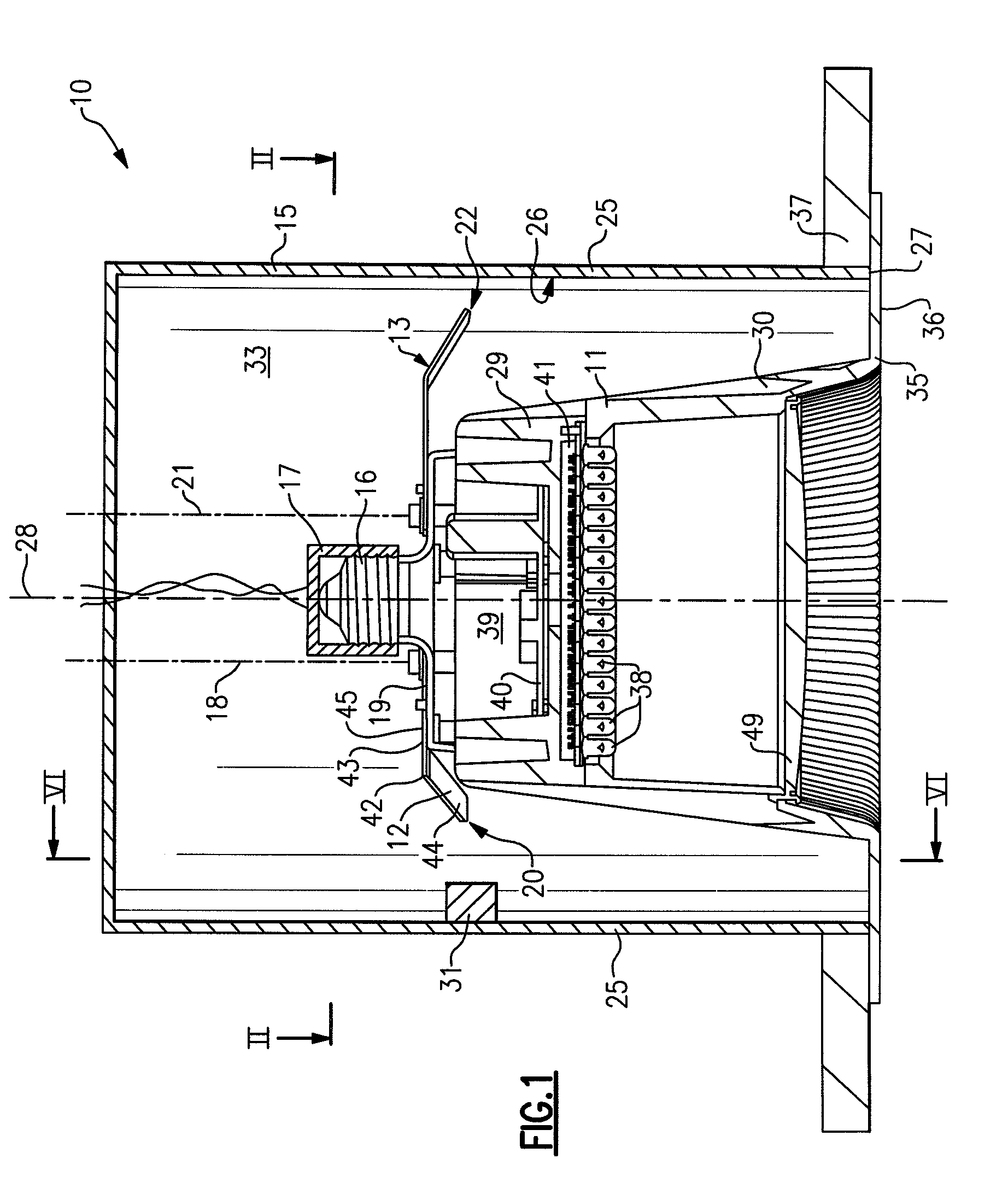
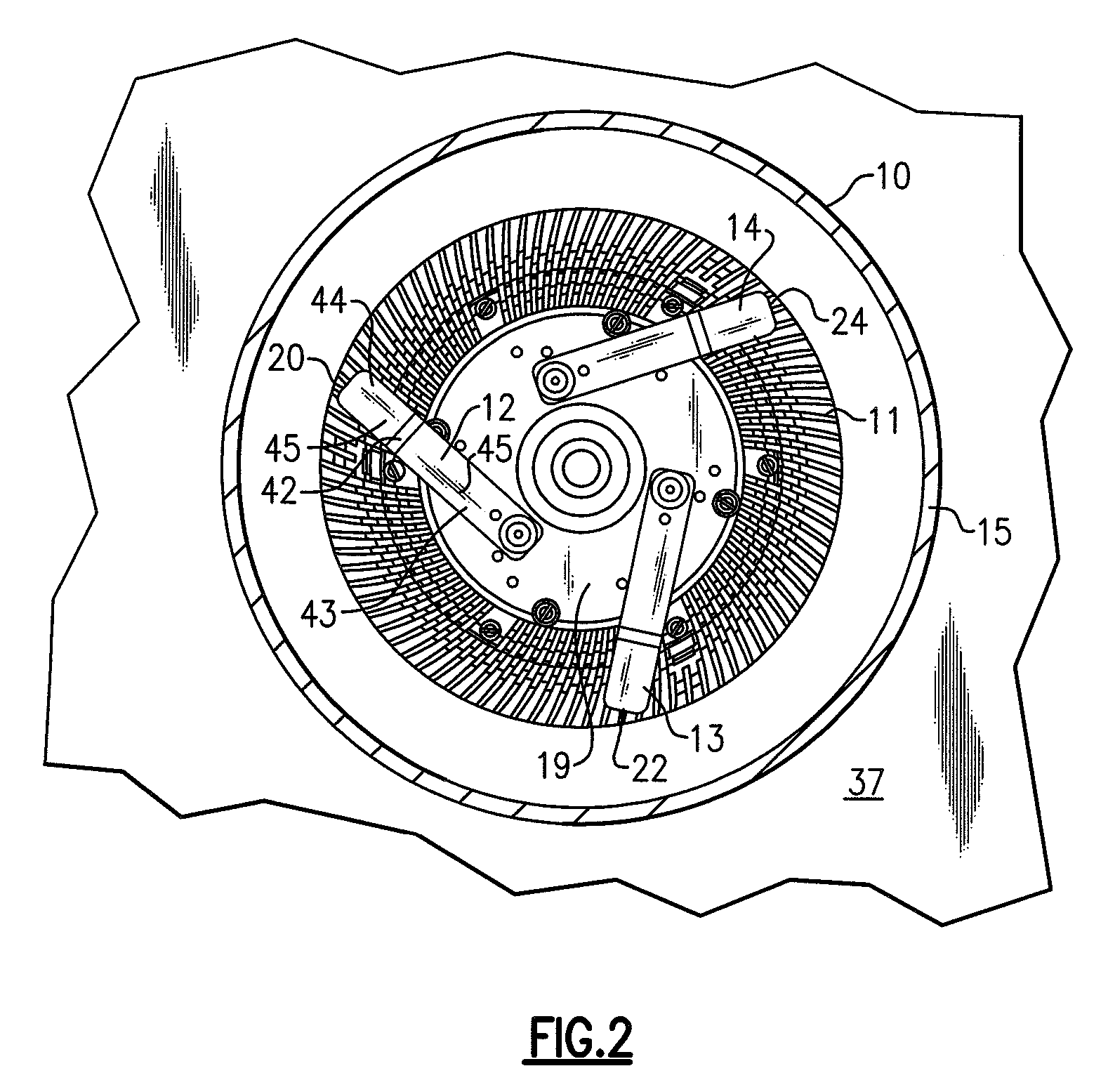
[0164]FIGS. 1-5 depict a lighting device in accordance with the present inventive subject matter. Referring to FIG. 1, there is shown a lighting device 10 which comprises a light engine housing 11, a flange portion 35, a first mounting clip 12, a second mounting clip 13, a third mounting clip 14 (not visible in FIG. 1) and a lighting device housing 15.

[0165] The light engine housing 11 comprises a screw-threaded electrical connection region 16 which is engaged in an electrical receptacle 17 (in the embodiment depicted, the electrical receptacle is an Edison socket).

[0166] The first mounting clip 12 is mounted pivotally about a first pivot axis 18 on a mounting clip surface 19 of the light engine housing 11. The first mounting clip 12 has a first mounting clip first end region 20 which is spaced from the first pivot axis 18.

[0167] Similarly, the second mounting clip 13 is mounted pivotally about a second pivot axis 21 on the mounting clip surface 19 of the light engine housing 11. ...

second embodiment

[0183]FIG. 7 depicts a lighting device in accordance with the present inventive subject matter. Referring to FIG. 7, there is shown a lighting device 70 which comprises a lighting device housing 71, a trim element 72, a first mounting clip 73 and a second mounting clip 74.

[0184] The lighting device housing 71 comprises an electrical receptacle 75 (in the form of an Edison socket) and a sidewall 76 having an internal surface 77, the internal surface 77 defining an internal space 78, the sidewall 76 terminating in a sidewall end region 79.

[0185] The trim element 72 comprises a first portion 80 and a second portion 81, the first portion 80 of the trim element 72 being positioned within the internal space 78, the second portion 81 of the trim element 72 extending beyond the internal space 78. The second portion 81 of the trim element comprises a second portion end region 82 which is positioned farther from an axis 83 of the internal surface 77 than the sidewall end region 79.

[0186] Th...

third embodiment

[0195]FIG. 15 is a perspective view of a lighting device according to the present inventive subject matter. Referring to FIG. 15, there is shown a lighting device housing including three mounting clips 120, 121, 122. For each mounting clip, there is provided a first stop 123, a first protrusion 124, a second protrusion 125 and a second stop 126. Each mounting clip includes a recess 128 (each faces downward). The clips 120, 121, 122 are all in the first position in FIG. 15. Each first stop 123 holds the respective clip in place, i.e., prevents it from moving toward the second position. When it is desired to move the clips 120, 121, 122 into the second position, the clips are bent upward slightly so that they can clear the first stop 123, and they are pivoted clockwise about their respective axes 127 and then released such that their respective recesses 128 rest over the respective first protrusions 124, and the clips are prevented from moving back to the first position by the respect...


PUM


Abstract

A lighting device, comprising a housing and at least one mounting clip. The housing comprises an electrical connection region engageable in an electrical receptacle. The mounting clip is pivotable from a first position, where an end region of the mounting clip does not extend beyond a periphery of the housing, to a second position, where the end region extends beyond the housing periphery. Also, a lighting device, comprising a housing, a trim element and at least one mounting clip. The mounting clip is pivotable, such that if the mounting clip is in a second position and then the trim element is rotated, the mounting clip will pivot to a third position, where the mounting clip engages the housing such that the trim element is biased toward a ceiling or other structure in which the lighting device is mounted. Also, methods of installing housings and / or trim elements.

Description

CROSS-REFERENCE TO RELATED APPLICATIONS [0001] This application claims the benefit of U.S. Provisional Patent Application No. 60 / 853,589, filed Oct. 23, 2006, the entirety of which is incorporated herein by reference.FIELD OF THE INVENTION(S) [0002] The present inventive subject matter relates to lighting devices which in some aspects include at least one pivotable mounting clip for holding a light engine housing or a trim element in place relative to a lighting device housing. The present inventive subject matter also relates to methods of installing a light engine housing in a lighting device housing, and methods of installing a trim element in a lighting device housing. BACKGROUND OF THE INVENTION(S) [0003] A large proportion (some estimates are as high as twenty-five percent) of the electricity generated in the United States each year goes to lighting. Accordingly, there is an ongoing need to provide lighting which is more energy-efficient. It is well-known that incandescent lig...

Claims


Application Information

Patent Timeline
Patent Type & Authority Applications(United States)
IPC IPC(8): F21S8/00
CPCF21S8/026F21S48/328F21V21/04F21V29/74F21Y2101/02F21V29/713F21V29/004F21Y2115/10F21V29/89F21V15/01
Inventor TROTT, GARY DAVIDPICKARD, PAUL KENNETH
Owner IDEAL IND LIGHTING LLC
Why Eureka
Try Eureka