
Method and device for reducing a size of a scanning device

a scanning device and size reduction technology, applied in the field of scanning methods, can solve the problems of large imaging distance required between the unit and the target, inability to meet other requirements, and complex and expensive quality scan mechanisms, etc., and achieve the effect of increasing the imaging distance and reducing the overall device siz

Active Publication Date: 2010-11-16
LEXMARK INT INC
View PDF34 Cites 0 Cited by
  • Summary
  • Abstract
  • Description
  • Claims
  • Application Information

AI Technical Summary

Benefits of technology

This solution enables the scanning device to maintain a compact size while achieving the necessary imaging distance for high-quality image capture, reducing the overall device size and cost by allowing the housing to collapse after scanning and utilizing reflective members to extend the imaging distance.

Problems solved by technology

Quality scans require intricate mechanisms which are often costly and complex.
A device meeting other requirements may not be acceptable because of a higher price.
A drawback of imaging units is the relatively large imaging distance required between the unit and the target.
This imaging distance requirement has prevented imaging units from being utilized within scanning devices.

Method used


Image

  • Method and device for reducing a size of a scanning device
  • Method and device for reducing a size of a scanning device
  • Method and device for reducing a size of a scanning device

Examples


Embodiment Construction

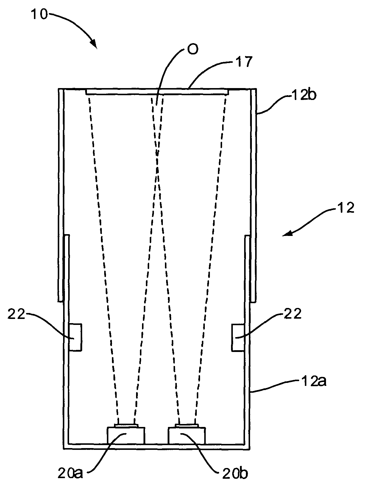
[0026]The present application discloses embodiments for using an imaging unit within a scanning device. The scanning device includes an imaging unit and a target bed for placement of the target document. The scanning device may include a housing that extends around the internal components, including the imaging unit. The housing is constructed to accommodate the imaging distance required between the imaging unit and target bed while keeping the size of the scanning device as small as possible.

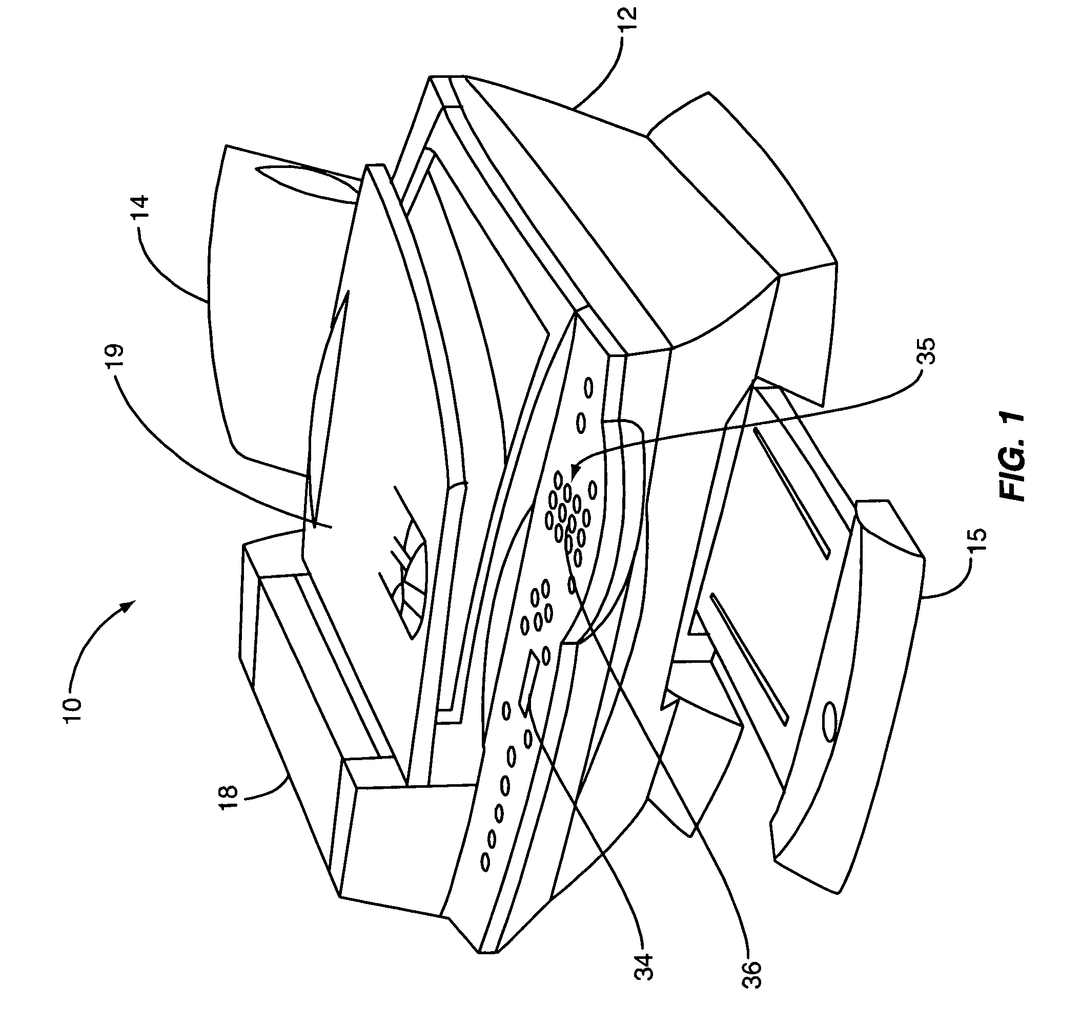
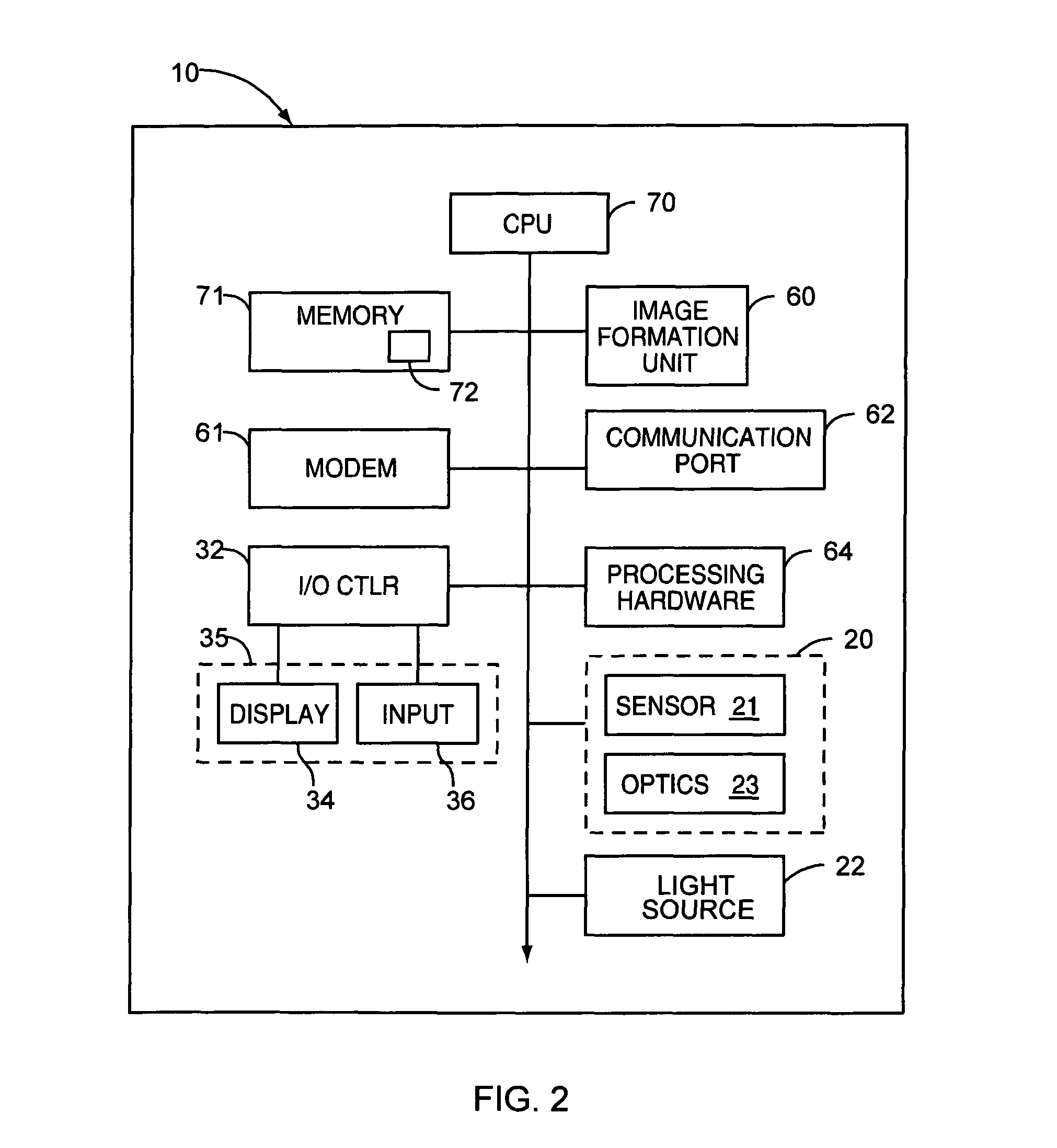
[0027]One embodiment of a scanning device is illustrated in FIG. 1 and indicated generally by the numeral 10. This embodiment features both scanning and image formation capabilities. Scanning device 10 comprises an exterior housing 12, a user interface 35, an imaging unit (not visible in FIG. 1), at least one media input tray 14 adapted to hold a stack of print media, a media output tray 15, and a document handler 18. In one embodiment, the document handler 18 is integrated into a cover 19 that...


PUM


Abstract

Scanning devices and method of use that accommodate a longer imaging distance while minimizing the size of the device. The scanning device may include an imaging unit having a sensor and optics. The scanning device may further include a target bed for placement of the targeted documents. An imaging distance extends between the imaging unit and the target bed. In one embodiment, the housing may be collapsed after the scanning procedure to reduce the overall device size. Reflective members may also be positioned within the interior of the device to lengthen the imaging distance. Still further embodiments may include a movable imaging unit.

Description

CROSS REFERENCES TO RELATED APPLICATIONS[0001]NoneSTATEMENT REGARDING FEDERALLY SPONSORED RESEARCH OR DEVELOPMENT[0002]None.REFERENCE TO SEQUENTIAL LISTING, ETC[0003]None.BACKGROUND[0004]1. Field of the Invention[0005]The present invention relates generally to scanners and scanning methods, and more particularly to those allowing for a reduced size scanner.[0006]2. Description of the Related Art[0007]Scanning devices are used in a variety of applications. Scanning devices may be combined in an all-in-one unit that includes scanning, image formation, and facsimile function. Scanning devices may also be independent and only capable of scanning documents. Historically, scanning devices include a drive mechanism that moves a scan bar across a target document. Each line of the document is individually scanned and the data is downloaded to a processor. This data is combined together to form a final two dimensional image of the document. These scanning devices require precise movement of t...

Claims


Application Information

Patent Timeline
Patent Type & Authority Patents(United States)
IPC IPC(8): H04N1/04H04N1/46
CPCH04N1/00525H04N1/00535
Inventor CHELVAYOHAN, MAHESANCROLEY, DONALD F.
Owner LEXMARK INT INC
Learn More