Image forming apparatus

a technology of image bearing members and forming apparatuses, which is applied in the direction of electrographic process apparatus, instruments, optics, etc., can solve the problems of affecting the stability the deterioration of the transfer receiving member and the drum, so as to achieve simple constitution and increase the distance of the image bearing member

Active Publication Date: 2014-08-21
CANON KK
View PDF5 Cites 0 Cited by
  • Summary
  • Abstract
  • Description
  • Claims
  • Application Information

AI Technical Summary

Benefits of technology

[0009]A principal object of the present invention is to provide an image forming apparatus capable of sufficiently increasing a distance of image bearing members for Y, M and C from a transfer receiving member during output of an image of, e.g., Bk in a relatively simple constitution without upsizing the image forming apparatus.

Problems solved by technology

However, according to this constitution, friction is generated between the fed transfer receiving member and the drums for the colors other than black, and therefore generates a problem such that the transfer receiving member and the drums are liable to deteriorate.
It would be also considered that in the case where the sufficient distance cannot be ensured, e.g., in the case where the transfer receiving member is in a waved state, the transfer receiving member contacts the drums for Y, M and C and thus the transfer receiving member and the drums are liable to deteriorate.

Method used


Image

  • Image forming apparatus
  • Image forming apparatus
  • Image forming apparatus

Examples


embodiment 1

(Image Forming Apparatus)

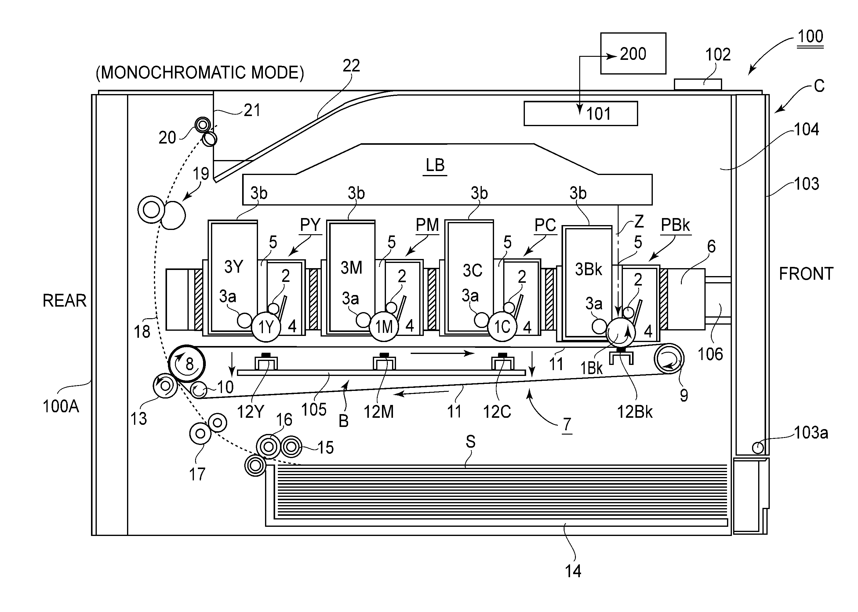
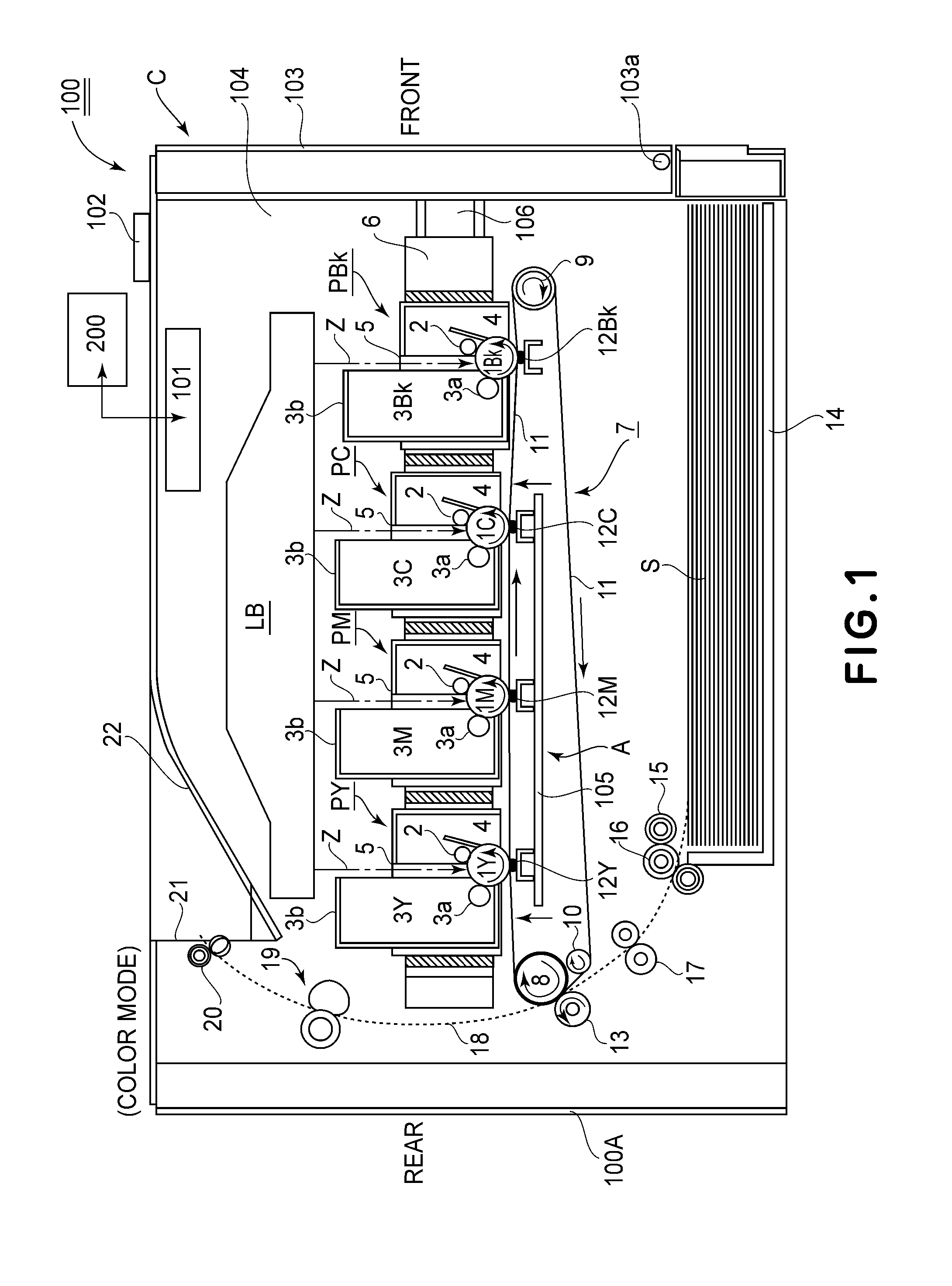
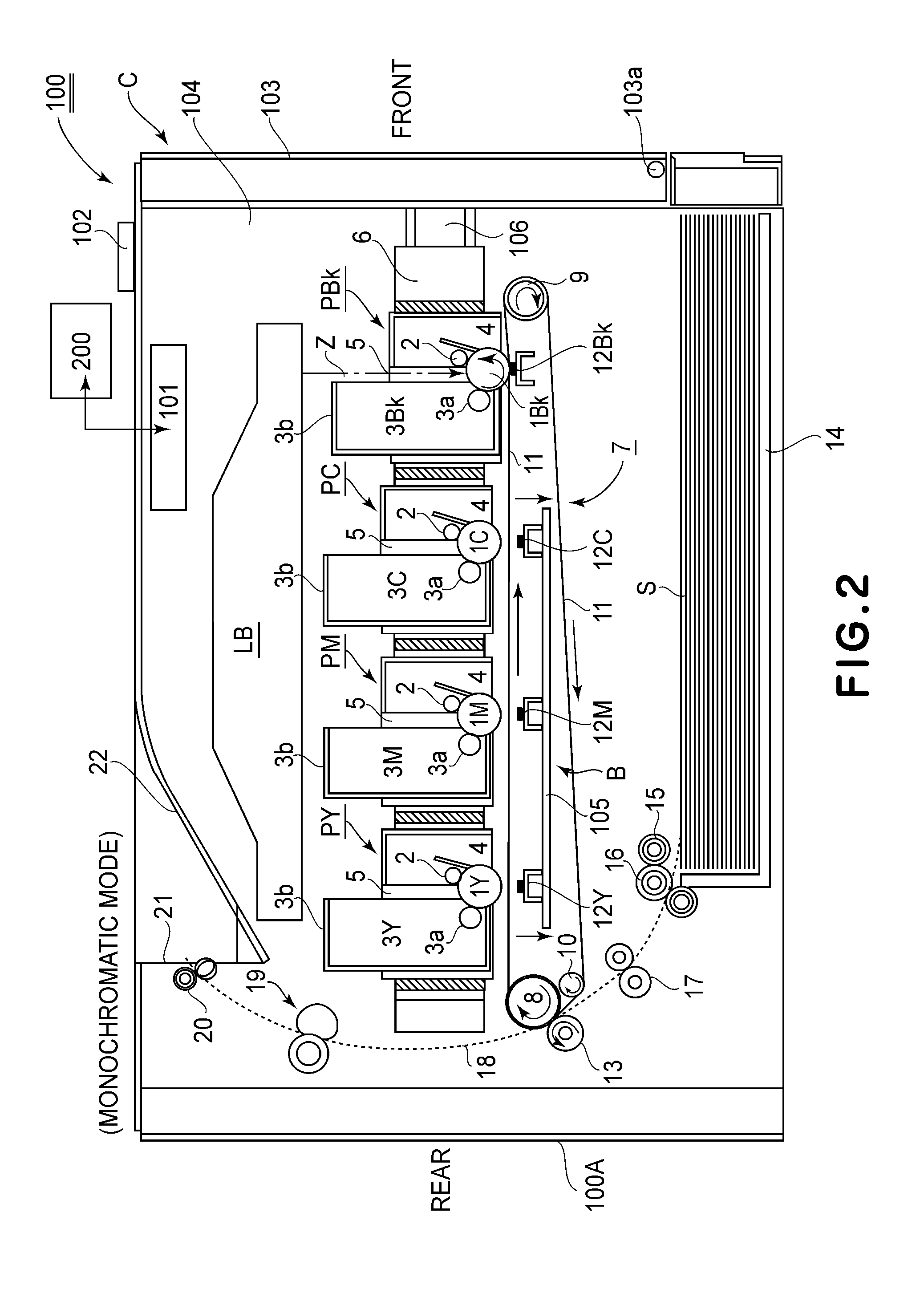
[0024]An image forming apparatus 100 according to this embodiment will be described with reference to FIG. 1 showing a schematic sectional view of the image forming apparatus. This image forming apparatus 100 is a full-color laser printer. That is, the image forming apparatus 100 forms a full-color image or a monochromatic image on a recording material S on the basis of image information (electric image signal) inputted from an external host device 200 into a control circuit portion (control means) 101. Incidentally, in the present invention, the image forming apparatus may be not only the printer but also another image forming apparatus such as a copying machine or a facsimile machine.

[0025]The external host device 200 is a personal computer, an image reader, the facsimile machine, a network system, a work station or the like. The image forming apparatus 100 includes an operating panel portion 102.

[0026]The image forming apparatus 100 is of a cartridge type...

embodiment 2

[0097]An image forming apparatus 100 according to Embodiment 2 will be described with reference to FIG. 10. In the image forming apparatus 100 in this embodiment, the tray 6 on which the first to fourth cartridges PY, PM, PC and PBk are supported in provided in an inclined state toward an obliquely lower-right ward direction in the apparatus main assembly 100A. That is, the tray 6 is disposed in the inclined state relative to the horizontal direction so that a downstream side thereof is lower than an upstream side thereof with respect to the pulling-out movement direction F.

[0098]With this disposition of the tray 6, also the intermediary transfer belt unit 7 is disposed in the inclined state so as to be in parallel to the inclined tray 6. The pulling-out movement direction F of the tray 6 from the apparatus main assembly 100A and the pushing-in movement direction G of the tray 6 into the apparatus main assembly 100A are set so as to be in parallel to a rectilinear line connecting th...


PUM


Abstract

An image forming apparatus includes: a first image bearing member; a plurality of second image bearing member; an endless belt opposing the first and second image bearing members; a driving roller; a supporting roller; a first transfer member opposing the first image bearing member; a plurality of second transfer members provided opposing the second image bearing members; and a supporting member for supporting the second transfer members. The supporting member is movable between a first position as a contact position and a second position as a spaced position. When image formation is effected in a state in which the supporting member is positioned in the first position, a nip between the first image bearing member and the belt member is positioned closer to a side where the supporting roller is positioned than a rectilinear line connecting contact positions of the belt member with the second image bearing members.

Description

FIELD OF THE INVENTION AND RELATED ART[0001]The present invention relates to an image forming apparatus of an electrophotographic image forming type or the like in which an image is formed on a recording material (medium). Particularly, the present invention relates to an image forming apparatus of a tandem type including a plurality of rotatable image bearing members which are successively arranged in a predetermined direction and on which images different in color are to be formed.[0002]Here, the image forming apparatus forms the image on the recording material by using an electrophotographic image forming process or the like. As the image forming apparatus, there are, e.g., a copying machine, a printer (e.g., a color LED printer) a facsimile machine, and a word processor. Further, on the recording material, the image is formed by the image forming apparatus, and the recording material may include, e.g., a sheet, an OHT sheet, and the like (hereinafter referred to as the sheet).[0...

Claims


Application Information

Patent Timeline
Patent Type & Authority Applications(United States)
IPC IPC(8): G03G15/01
CPCG03G15/65G03G15/0189G03G2215/0132G03G2215/0193
Inventor SUZUKI, TETSUJIKAWANAMI, TAKEOAMANO, MASAO
Owner CANON KK
Why Eureka
Try Eureka