Large-field-of-view correlated imaging device and imaging method

A technology of correlative imaging and large field of view, which is applied in the directions of measurement devices, electromagnetic wave re-radiation, and utilization of re-radiation, can solve problems such as motion blur, high light energy loss, and unfavorable long-distance target detection, so as to improve the scope of application, Improving the imaging distance and reducing the difficulty of assembly

Pending Publication Date: 2021-04-09
苏州蛟视智能科技有限公司
View PDF0 Cites 0 Cited by
  • Summary
  • Abstract
  • Description
  • Claims
  • Application Information

AI Technical Summary

Problems solved by technology

However, the existing correlative imaging technology still has the following problems: 1. The high-energy laser light output by the light source is modulated by the spatial light modulation device, and the light energy loss is high, which is not conducive to the expansion of the imaging distance; 2. The beam passes through the projection unit with a certain The divergence angle propagates to the front of the device, and the light energy density has an inverse square relationship with the increase of the propagation distance, which is not conducive to the detection of long-distance targets; 3. Although the small field of view of the device can realize high-definition imaging of long-distance local areas, when the device is placed Vehicles, robots, airplanes and other vehicles with frequently changing motion states, the drastic changes in the imaging range will lead to many problems such as inability to aim at the target, motion blur, etc., which reduces the practicability of the system; 4. Expand the field of view by modifying the optical parameters of the projection unit field, the light energy density will drop significantly with the increase of the field of view size, shortening the detection distance of the device

Method used


Image

  • Large-field-of-view correlated imaging device and imaging method
  • Large-field-of-view correlated imaging device and imaging method
  • Large-field-of-view correlated imaging device and imaging method

Examples


Embodiment 1

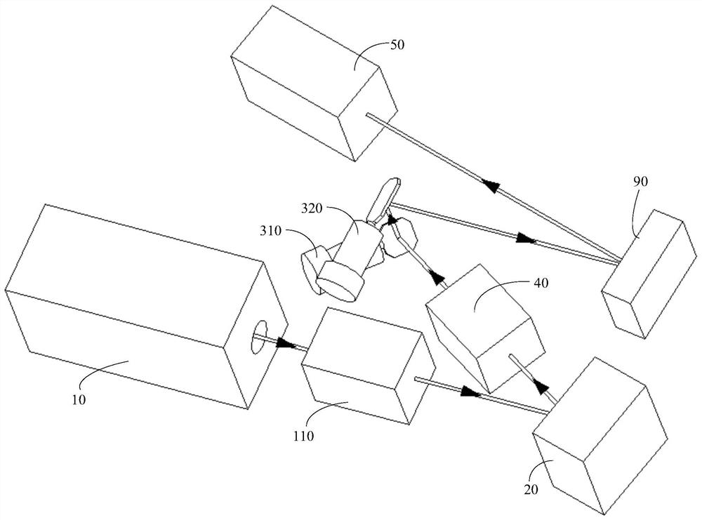
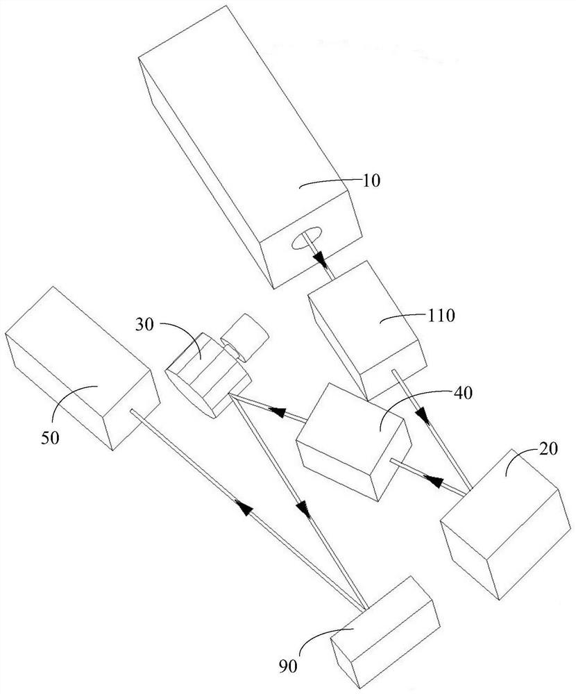
[0031] Such as figure 1 As shown, the present invention provides a large field of view associated imaging device, including a pulsed light source 10, a light modulation unit 20, a directional scanning projection unit, a light receiving unit 50, a central processing unit 60, and a display unit 70 arranged sequentially along the optical path. And the control unit 80 connected with the light modulation unit 20, the directional scanning projection unit, and the central processing unit 60, the pulsed light source 10 generates a pulse beam and projects it to the light modulation unit 20 and the directional scanning projection unit in sequence On the detection target 90, the reflected light of the detection target 90 is received by the light receiving unit 50 and transmitted to the central processing unit 60, and the central processing unit 60 synchronously receives the data of the control unit 80 and the light receiving unit 50 The correlation calculation is performed to obtain the ...

Embodiment 2

[0043] Different from Embodiment 1, this embodiment provides an imaging method for a large field of view associated imaging device as described above, including the following steps:

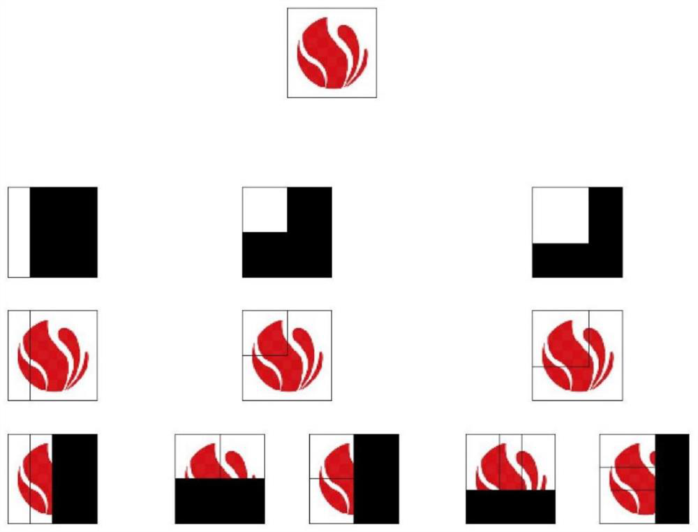
[0044] S1: Divide the detection target 90 into N field of view partitions, which are respectively the first field of view partition, the second field of view partition ... the Nth field of view partition, N is a positive integer, wherein the first field of view partition, the second field of view partition Partitions... The order of the Nth field of view partitions can be marked sequentially from top to bottom or from left to right, or can be marked in other ways, as long as a complete image can be assembled in the end.

[0045] S2: The pulsed light source 10 generates a pulsed beam and is modulated by the light modulation unit 20 in sequence, and then irradiates the first field of view partition in the detection target 90 after being modulated by the directional scanning projection unit, and the ...

Embodiment 3

[0054] Different from Embodiment 1, this embodiment provides an imaging method for a large field of view associated imaging device as described above, including the following steps:

[0055] S1: Divide the detection target 90 into N field of view partitions, which are respectively the first field of view partition, the second field of view partition ... the Nth field of view partition, N is a positive integer, wherein the first field of view partition, the second field of view partition Partitions... The order of the Nth field of view partitions can be marked sequentially from top to bottom or from left to right, or can be marked in other ways, as long as a complete image can be assembled in the end.

[0056] S2: The pulsed light source 10 generates a pulsed beam and is modulated by the light modulation unit 20 in sequence, and then irradiates the first field of view partition in the detection target 90 after being modulated by the directional scanning projection unit, and the ...


PUM


Abstract

The invention discloses a large-field-of-view correlated imaging device and an imaging method. The imaging device comprises a pulse light source, a light modulation unit, a directional scanning projection unit, a light receiving unit, a central processing unit, a display unit, which are sequentially arranged along a light path, and a control unit connected with the directional scanning projection unit, the light modulation unit and the central processing unit. The divergence angle of an emergent light beam is adjusted through the directional scanning projection unit, so that light energy intensively irradiates a local area of a field of view to obtain an extremely high signal-to-noise ratio, and the imaging distance is increased. According to the invention, any large-range view field imaging can be achieved by setting the types and parameters of the light beam directional scanning mechanisms and combining the image splicing technology, the application range of the device is widened, view field expansion can be achieved only through one or a few scanning mechanisms, and the device is low in machining and assembling difficulty and high in stability. The image resolution of the imaging device is determined by the light modulation unit, and the directional scanning mechanism does not influence the image resolution.

Description

technical field [0001] The invention relates to the field of target detection, identification and imaging, in particular to a large field of view associated imaging device and an imaging method. Background technique [0002] Time-of-flight (TOF)-based laser imaging radar has the capability of over-the-horizon three-dimensional detection, and is an indispensable detection method for future applications such as intelligent driving, remote sensing mapping, intelligent monitoring, and scene reproduction. [0003] At present, the commonly used laser imaging radar adopts the "point-to-point" direct information acquisition mode. Multi-line imaging is achieved through multiple sets of "transmit-receive" units combined with mechanical scanning or beam deflection devices. On the one hand, this imaging method has a limited imaging distance, and the resolution of long-distance imaging is extremely low; on the other hand, the system requires high precision optical machining and alignmen...

Claims


Application Information

Patent Timeline
IPC IPC(8): G01S17/89
CPCG01S17/89
Inventor 韩捷飞孙立颖李丽丽范国华陈兵兵
Owner 苏州蛟视智能科技有限公司
Why Eureka
Try Eureka