Check patentability & draft patents in minutes with Patsnap Eureka AI!

Telescope multiple discrete segment primary mirror

a technology of primary mirror and telescope, which is applied in the field of telescopes, can solve the problems of compromising the purpose of the telescope, affecting the performance of the telescope, and the absorption of some spectrum, and achieve the effect of achieving the effect of varying performance characteristics

Inactive Publication Date: 2010-11-23
WATTERS GEORGE
View PDF9 Cites 0 Cited by
  • Summary
  • Abstract
  • Description
  • Claims
  • Application Information

AI Technical Summary

Benefits of technology

This configuration allows for a lighter and more versatile primary mirror that can be assembled in space, providing comparable performance to a monolithic mirror while enabling observation across a broader spectral range, reducing weight and cost, and allowing for the replacement of defective segments without replacing the entire mirror surface.

Problems solved by technology

Thus, chromatic aberration, the focusing of light of different wavelengths occurring at different focal points, occurs in uncorrected lenses, causing the creation of an aberration-free large lens to be a costly process.
Collection and transmission of the spectrum of light is an important role of a telescope, and thus absorption of some portion of the spectrum compromises the purpose of the telescope.
Larger mirrors, however, require an elaborately complex structural support system to keep the structure of the mirror from collapsing under its own enormous weight.
As the size swells, therefore, the cost of the mirror becomes exorbitant.
An additional issue with weight is the cost of sending such weight into space.
Thus, when the Hubble Space Telescope's launch in 1990 placed a reflective mirror in an orbit about Earth, the size of the objective mirror was limited in a “weight versus cost” decision.
Thus, with the availability of computer control, it was not necessary to create a single, rigid, monolithic 10-m diameter piece of glass, which would be very difficult or impossible to deal with.
However, the Keck design still suffers from a vast shortcoming.
All coatings suffer from the fact that a coating can only be optimized to reflect a portion of the spectrum.

Method used


Image

  • Telescope multiple discrete segment primary mirror
  • Telescope multiple discrete segment primary mirror
  • Telescope multiple discrete segment primary mirror

Examples


Embodiment Construction

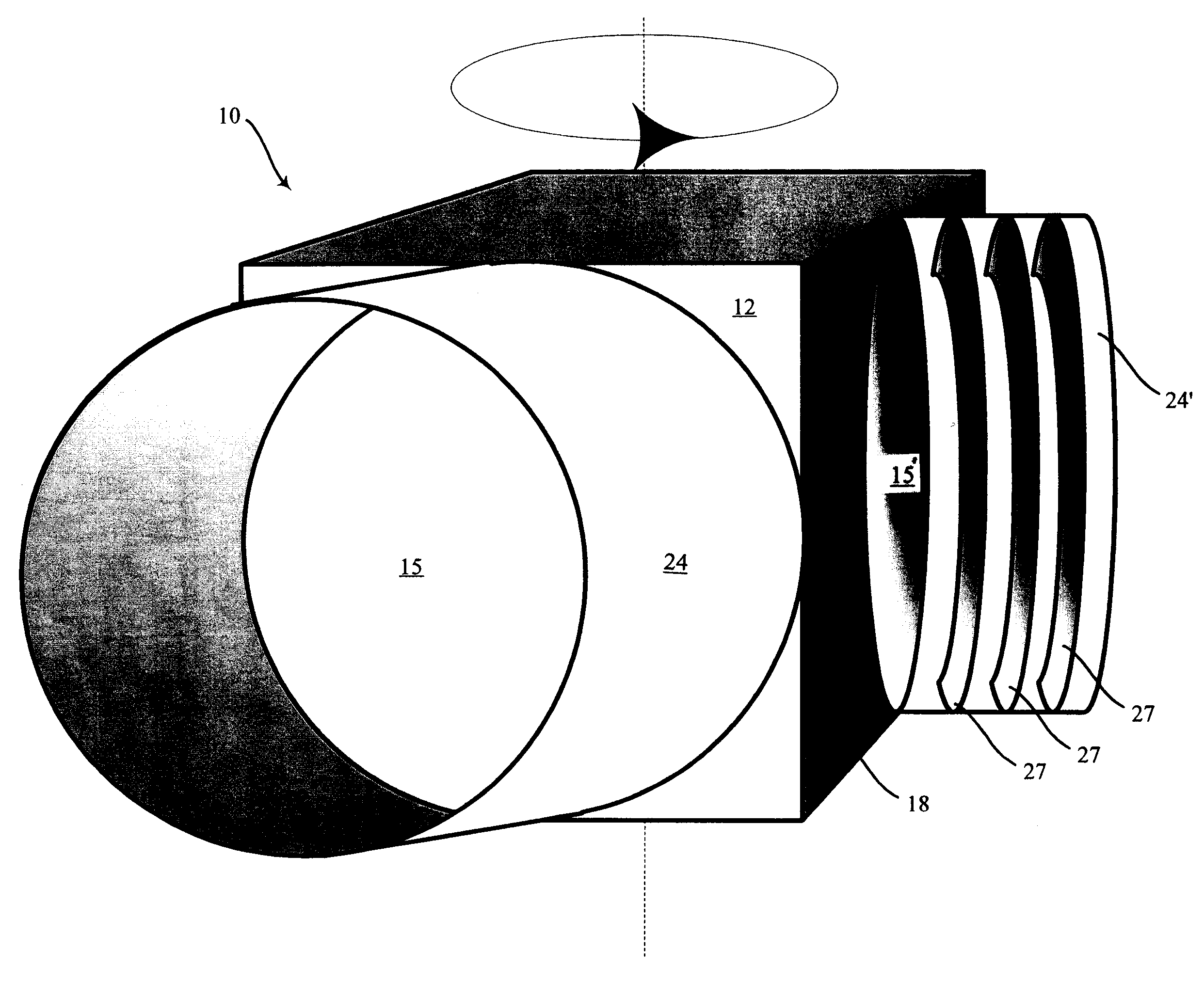
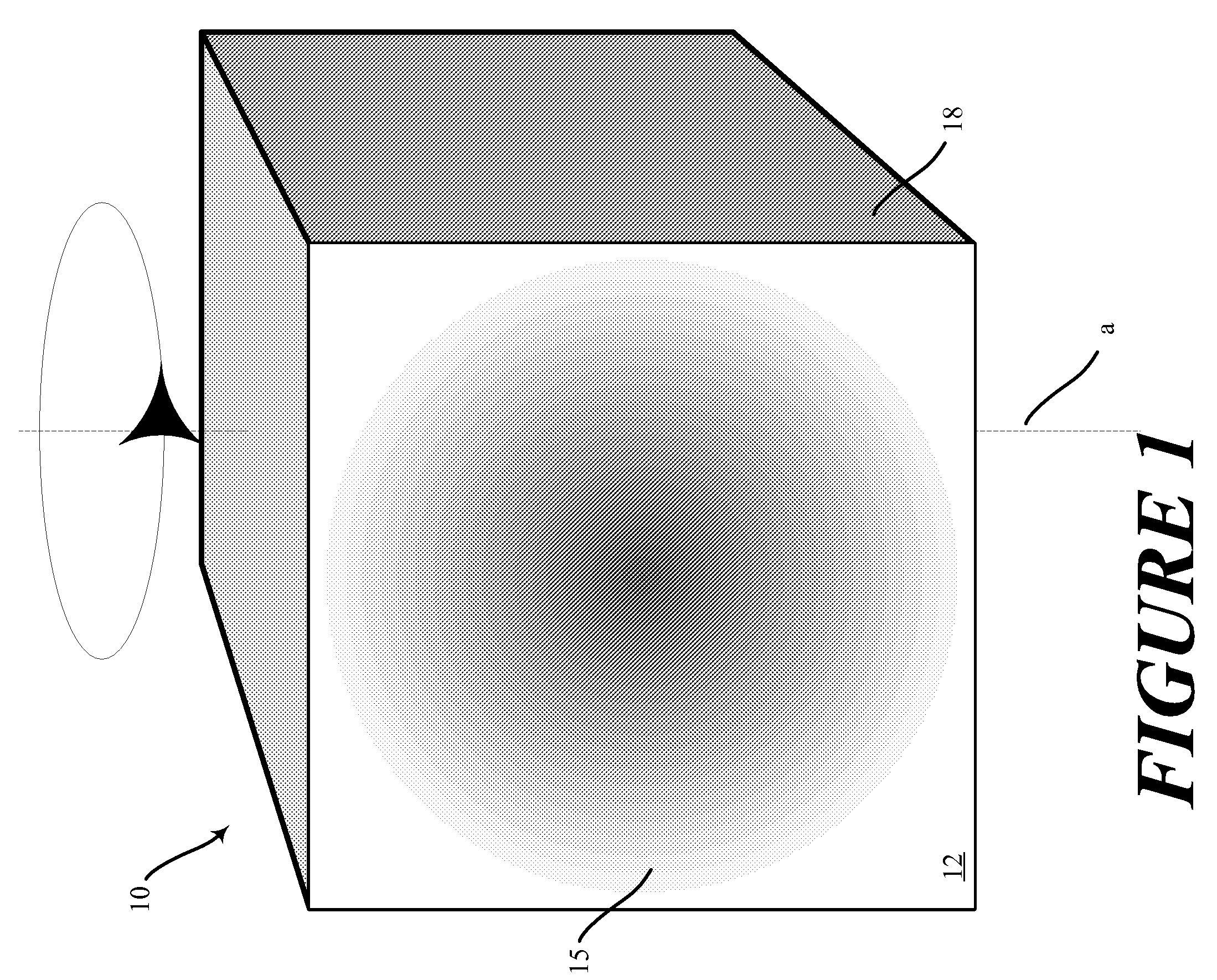
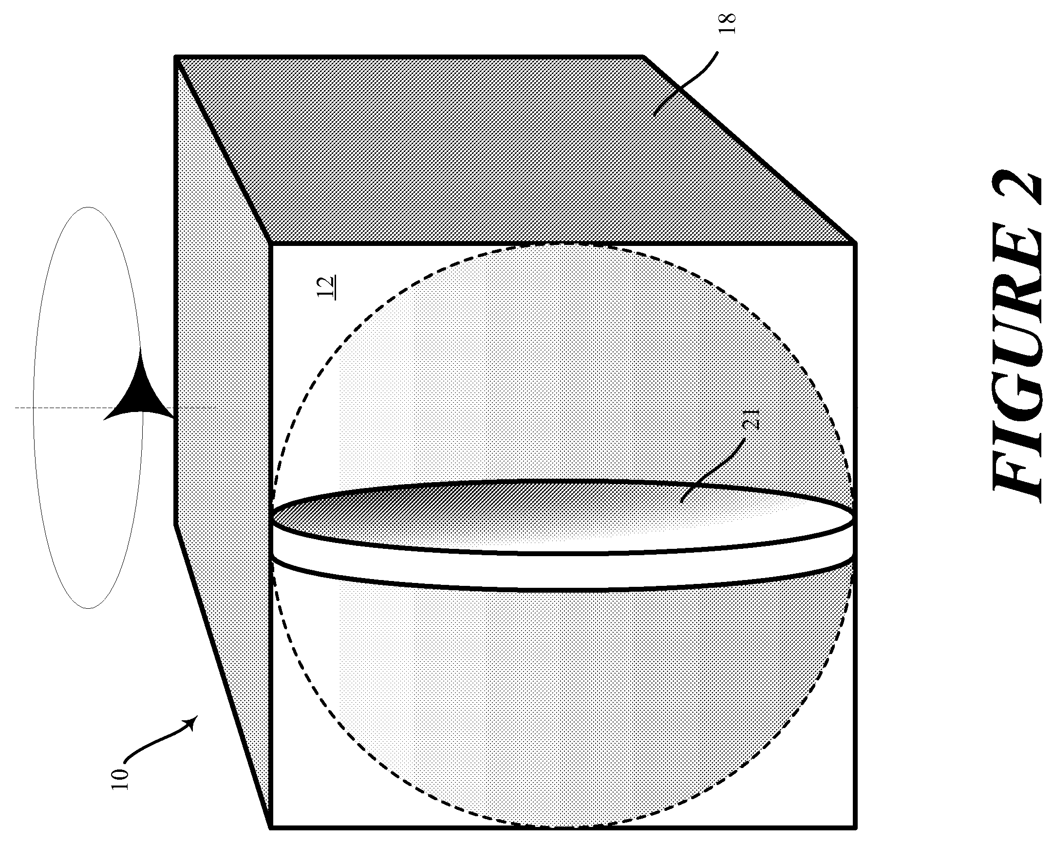
[0029]Referring to FIG. 1, a primary mirror (or primary) is the principal light-gathering surface of a reflective telescope. A mirror segment 10 is a convex regular polyhedron mounted to rotate about an axis a. For purposes of non-limiting explanation, the mirror segment is portrayed as a cube and the axis a is shown to intersect a first square face of the cube at the center of the square face passing out of the cube in the center of a second square face in opposing relation to the first square face. The mirror segment 10 is thereby allowed to rotate in only about a single axis. This exemplary embodiment will be shown in the succeeding diagrams in order to clearly set forth the advantages of the inventive solution.

[0030]Nonetheless, any convex polyhedron may suitably serve as a mirror segment. Regular convex polyhedrons give the advantage of having multiple congruent faces, each of equal area. One group of regular convex polyhedrons is a group of five polyhedrons consisting of the t...


PUM


Abstract

A method and apparatus is configured for reflecting a beam of light incident at a primary mirror by rotating a first mirror segment to align a selected facet of the mirror segment to be generally orthogonal to the principal axis. The first mirror segment is translated in a motion parallel to the principal axis to a first position such that the mirrored segment at a facet comprising a mirror is brought into alignment with at least one second mirrored segment to form at a facet a first parabolic mirror. The incident beam of light is then reflected by collimating the first parabolic mirror by rotation and translation of the first mirror segment to strike a first secondary element.

Description

FIELD OF THE INVENTION[0001]This invention relates generally to reflective telescopes and, more specifically, to the primary mirror segment technology.BACKGROUND OF THE INVENTION[0002]A reflecting telescope (reflector) is an optical telescope which uses a combination of curved or plane (flat) mirrors to reflect light and form an image (catoptric), rather than lenses to refract or bend light to form an image (dioptric).[0003]A curved primary mirror is the reflector telescope's basic optical element which creates an image at the focal plane. The distance from the mirror to the focal plane is called the focal length. Film or a digital sensor may be located here to record the image, or an eyepiece for visual observation.[0004]Mirrors eliminate chromatic aberration but still produce other types of aberrations. In general, on axis they produce spherical aberration—the outer and inner zones of the telescope do not share a common focus. This was the construction flaw in the Hubble Space Tel...

Claims


Application Information

Patent Timeline
Patent Type & Authority Patents(United States)
IPC IPC(8): G02B5/08
CPCB64G1/105G02B7/183G02B17/002G02B17/0694G02B23/16G02B27/0018
Inventor WATTERS, GEORGE
Owner WATTERS GEORGE
Features
  • R&D
  • Intellectual Property
  • Life Sciences
  • Materials
  • Tech Scout
  • Unparalleled Data Quality
  • Higher Quality Content
  • 60% Fewer Hallucinations
Learn More