Colour sensor arrangement and method for colour sensor calibration

a colour sensor and colour sensor technology, applied in the field of colour sensor arrangement and method for colour sensor calibration, can solve the problems of not being able to provide very accurate devices, unable to meet the standard colour-matching function, and unable to reduce the variance by itself, etc., to achieve accurate xyz tristimulus, accurate device-to-device tolerance, and high device-to-device tolerance

Active Publication Date: 2016-08-25
AMS AG
View PDF5 Cites 7 Cited by
  • Summary
  • Abstract
  • Description
  • Claims
  • Application Information

AI Technical Summary

Benefits of technology

[0018]The colour sensor arrangement allows for very accurate device-to-device tolerances which can be achieved natively for third-party colour transformations. Colour transformations such as the CIE XYZ tristimulus values are often the desired output of a colour sensor device. According to the presented disclosure, standard process manufacturing techniques (e.g. without the use of custom filters) can be used to achieve a very high device-to-device tolerance and an accurate XYZ tristimulus (or some other colour transformation coordinate) output on-chip by generating the coefficients from an algorithm, such as CIE XYZ tristimulus matrix transformation, then storing them in non-volatile memory so that the coefficient

Problems solved by technology

Given the complexity of transforming, for example, RGB counts per μw cm2 to CIE XYZ tristimulus colour space, decreasing the variance will not likely by itself address the desired degree of accuracy.
Unfortunately, the colour filter spectr

Method used


Image

  • Colour sensor arrangement and method for colour sensor calibration
  • Colour sensor arrangement and method for colour sensor calibration

Examples


Embodiment Construction

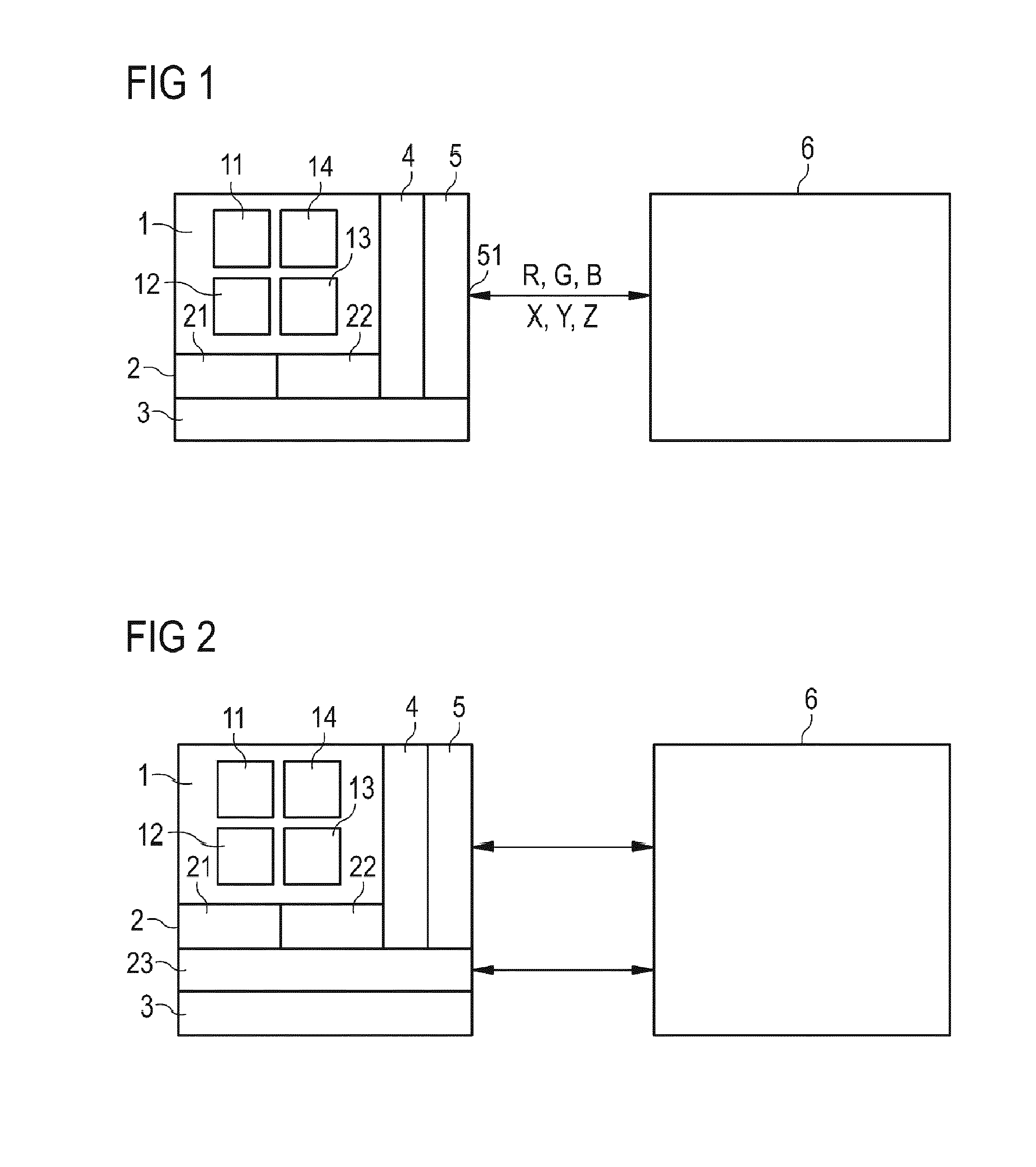
[0039]FIG. 1 depicts a general scheme of an embodiment of the colour sensor arrangement. The colour sensor arrangement comprises a colour sensor 1, a processing unit 2, a memory 3, a control unit 4, and an interface 5.

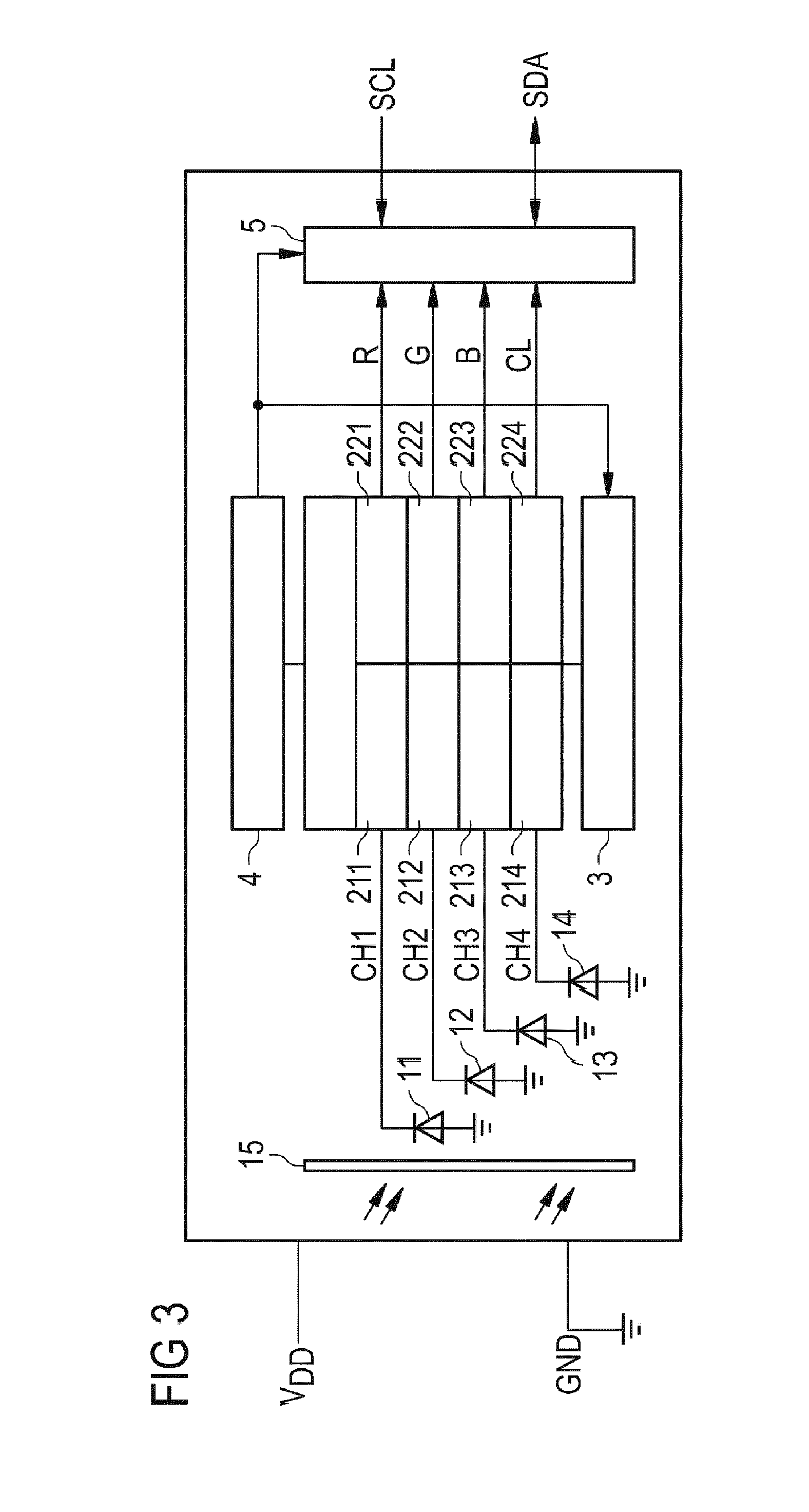
[0040]The colour sensor 1 further comprises an array of photo elements which, in this particular embodiment, comprises a first, second, third, and fourth photodiode 11, 12, 13, 14. The first, second, and third photodiodes (11, 12, 13) are covered by a first, second and third filter, respectively (not shown). The pass band of the first, second and third filter are adjusted so that they pass only a certain band of light. For example, the first filter has a pass band in the red, the second filter in the green, and the third filter in the blue part of the visible electromagnetic spectrum. The fourth photodiode 14 is not covered by a filter. Alternatively, however, also the fourth photodiode can be covered by a filter having a band according to a yet another part of the vis...


PUM


Abstract

A colour sensor arrangement comprises a colour sensor arranged to generate at least a first channel signal being indicative of a colour of light incident on the colour sensor. A processing unit is connected to the colour sensor and arranged to generate a tuple of colour signals by processing the at least first channel signal. A memory is connected to the processing unit and a control unit is connected to the processing unit and to the memory. Furthermore, the control unit is arranged to receive calibration data relating the tuple of colour signals to a calibrated tuple of colour signals and arranged to store said calibration data (M) by means of the memory. An interface is connected to the processing unit and comprises an interface terminal.

Description

[0001]This disclosure relates to a colour sensor arrangement and to a method for colour sensor calibration.BACKGROUND OF THE INVENTION[0002]Colour sensing for the LED market is an emerging technology as companies are considering incorporating solutions into their portfolios. Conversely, the LED market is a fairly mature market with various manufacturers that include makers of LED modules, LED engines, luminaires, smartphones, flat panel TVs, laptops, etc. These manufacturers follow the performance standards established by a number of organizations including ANSI / ANSLG, CIE, IES, and NEMA for LED component manufacturers, luminaire manufacturers, etc. Many customers express a desire of having a colour sensor that can support high accuracy, e.g. a Δu′v′ of 0.001 to 0.002 which implies a very tight device-to-device tolerance. Given the complexity of transforming, for example, RGB counts per μw cm2 to CIE XYZ tristimulus colour space, decreasing the variance will not likely by itself add...

Claims


Application Information

Patent Timeline
IPC IPC(8): G01J3/02G01J3/51G01J3/46
CPCG01J3/513G01J3/0213G01J3/465G01J3/462G01J3/505G01J3/0297
Inventor LEE, GLENN
Owner AMS AG
Why Eureka
Try Eureka