Controlling Rules and Variables for Cutting

a control rule and variable technology, applied in the direction of welding apparatus, manufacturing tools, laser beam welding apparatus, etc., can solve the problems of bringing detail prices, ineffective methods for part placement, and huge waste, so as to optimize machine cost, reduce material waste, and reduce the effect of material was

Active Publication Date: 2012-08-02
TOMOLOGIC
View PDF5 Cites 8 Cited by
  • Summary
  • Abstract
  • Description
  • Claims
  • Application Information

AI Technical Summary

Benefits of technology

[0062]The advantages of a method, system, a computer program product according to the present invention are that through the invention it is possible to minimize the material waste and create a production reliable cutting plan with optimized machine cost, meaning an optimization regarding the number of piercings, position distances and cutting distances.
[0063]The present invention provides an optimal cutting with a cutting work plan where it is possible to control the cutting variables in the cutting machine to get a reliable process. The invention provides control over turning areas, distance between parts, micro joints between parts, when clustering together more than one free formed part, length and angle of lead in, length and angle of lead out, switching between tool radius compensations, and scanning within the cluster area, that is the possibility to use the sensing cutting head and without lifting the head between holes, splits, common cuts, and pockets within the cluster area, to minimize the positioning distances.
[0064]The provided production reliability means a safe process, right tolerance for parts, and an optimal quality for parts with minimum resource waste.
[0065]This present invention provides the possibility to create clusters for free form parts. Single parts optimized on the work area in close clusters provide a chance to minimize the material waste. As clusters are created details are positioned against each other which make it possible to use all tangent segments when clustering. The inventive cluster of several parts creates a new part without safe distance only tangents, splits, bridges, turning areas, micro joints, common cut lines and pockets. Different constellations of the inventive rules and variables provides the possibility to give a reliable cutting process for any kind of upcoming situation when free formed two dimensional parts are going to be clustered without safe distance.
[0066]The use of micro joints between the parts to be cut instead of between the parts and the skeleton also gives advantages in the manual or automated sorting process.
[0067]The use of inventive turning areas will also provide the possibility to avoid using areas of the skeleton for changing the cutting direction and instead use already cut lines where the cutting direction is changed, which again minimize the waste.

Problems solved by technology

With any kind of beam cutting technology there is a huge problem with waste.
The background to why the wastage incurred in production is the ineffective methods for part placement on the raw material in combination with technology rules for each cutting method and each material.
When cutting technology is used as production method there are four different costs that bring the detail price.
It is a problem to bring down the amount of waste material.
It is also a problem to limit the number of piercings that are required in a cutting process and it is a problem to optimize the position distances and the cutting distances in the cutting process.
It is a problem to minimize the distance between free shaped parts in order to minimize the waste material.
If parts are positioned very close to each other, it is also a problem to keep the number of piercings to a minimum, to provide turning areas for the beam cutting process and to avoid that parts will pivot if there is no neighboring skeleton that the part can be joined to.

Method used


Image

  • Controlling Rules and Variables for Cutting
  • Controlling Rules and Variables for Cutting
  • Controlling Rules and Variables for Cutting

Examples


Embodiment Construction

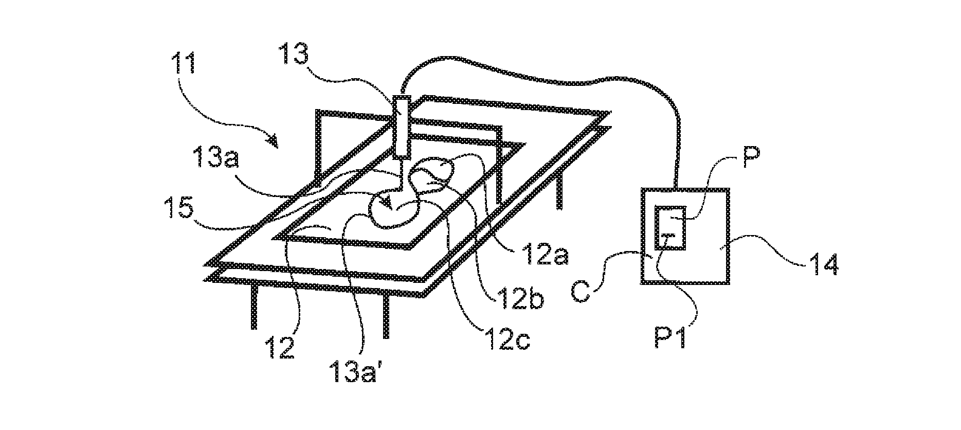
[0080]The present invention will now be described with reference to FIG. 1 illustrating a method for machine cutting several parts 12a, 12b, 12c out of a piece of material 12 using a beam cutting technology. The schematic illustration of FIG. 1 shows that a cutting device 13 is movable and the material 12 is fixed, however, it should be understood that the present invention can also be implemented in a system where the cutting device is fixed and the material is movable. The invention relates to controlling the relative movement between the material 12 and the cutting device 13 regardless of what is moving and what is fixed.

[0081]In the description of the present invention certain terminology might be used that implies that one specific beam cutting technology is described, but it should be understood that the present invention relates to any beam cutting technology and the skilled person will understand how a feature described with a terminology specific for one beam cutting techno...


PUM

PropertyMeasurementUnit
sizeaaaaaaaaaa
thicknessaaaaaaaaaa
sizeaaaaaaaaaa

Abstract

The present invention relates to a method and a system for machine cutting several parts (31, 32, 33, 34) out of a piece of material using a beam cutting technology. The invention provides a set of controlling rules and variables for cutting two dimensional shapes or patterns. One rule or a combination of several rules are used for the cutting operation depending on the shape or pattern to be cut, the shape or pattern forming the parts (31, 32, 33, 34) out of the piece of material. The present invention specifically teaches that the set of controlling rules comprises rules for the forming of a duster (3A) of parts with free form shapes, the parts being positioned so close to each other so that only the thickness of the cutting beam is found between adjacent parts whenever the shape of the parts allows it.

Description

FIELD OF INVENTION[0001]The present invention relates to a method for machine cutting several parts out of a piece of material using a beam cutting technology, the method providing a set of controlling rules and variables for cutting two dimensional shapes or patterns, where one rule or a combination of several rules are used for the cutting operation depending on the shape or pattern to be cut, the shape or pattern forming the parts out of the piece of material.[0002]The present invention also relates to a system and to a computer program product through which the inventive method can be implemented.[0003]There are various cutting technologies known to cut parts out of a piece of material and the present invention relates to what here is called beam cutting technology. Beam cutting is defined as having some kind of beam as the cutting agent, such as laser cutting, plasma cutting, ion beam cutting, flame or torch cutting, water cutting, pellet cutting or air cutting. This is not to ...

Claims


Application Information

Patent Timeline
Patent Type & Authority Applications(United States)
IPC IPC(8): B26D1/00B26D7/27
CPCB23K26/38Y10T83/849Y10T83/04
Inventor NORBERG OHLSSON, MAGNUS
Owner TOMOLOGIC
Why Eureka
Try Eureka