Method for precise molding and alignment of structures on a substrate using a stretchable mold

a technology of stretchable molds and structures, applied in the manufacture of electrode systems, cold cathode manufacturing, electric discharge tubes/lamps, etc., can solve the problems of difficult alignment across the substrate, the method is prone to elongation, and the method has the same disadvantages

Inactive Publication Date: 2006-01-10
3M INNOVATIVE PROPERTIES CO
View PDF78 Cites 24 Cited by
  • Summary
  • Abstract
  • Description
  • Claims
  • Application Information

AI Technical Summary

Benefits of technology

[0008]While direct molding offers less wasted material than sandblasting or lithography and fewer alignment steps than screen printing, it poses challenges such as releasing the mold consistently and repeatedly from the barrier rib material and fabricating a separate mold for each unique display substrate. For example, slight adjustments in barrier rib pitch dimensions are desired to account for variations in shrinkage factors of glass substrates due to, for example, different lots or different suppliers.
[0010]The present invention provides a method for forming and aligning microstructures on patterned substrates. Preferred embodiments of the present invention permit formation and alignment of microstructures on patterned substrates with high precision and accuracy over relatively large distances.

Problems solved by technology

While direct molding offers less wasted material than sandblasting or lithography and fewer alignment steps than screen printing, it poses challenges such as releasing the mold consistently and repeatedly from the barrier rib material and fabricating a separate mold for each unique display substrate.
If the barrier ribs are initially molded onto a transfer sheet, this method has the same disadvantages as direct molding.
One difficulty, however, is that when the mold and rib material are pressed against the substrate to adhere the rib material to the substrate, the mold tends to elongate.
This motion of the mold make precise alignment across the substrate very difficult.

Method used


Image

  • Method for precise molding and alignment of structures on a substrate using a stretchable mold
  • Method for precise molding and alignment of structures on a substrate using a stretchable mold
  • Method for precise molding and alignment of structures on a substrate using a stretchable mold

Examples


examples 1 and 2

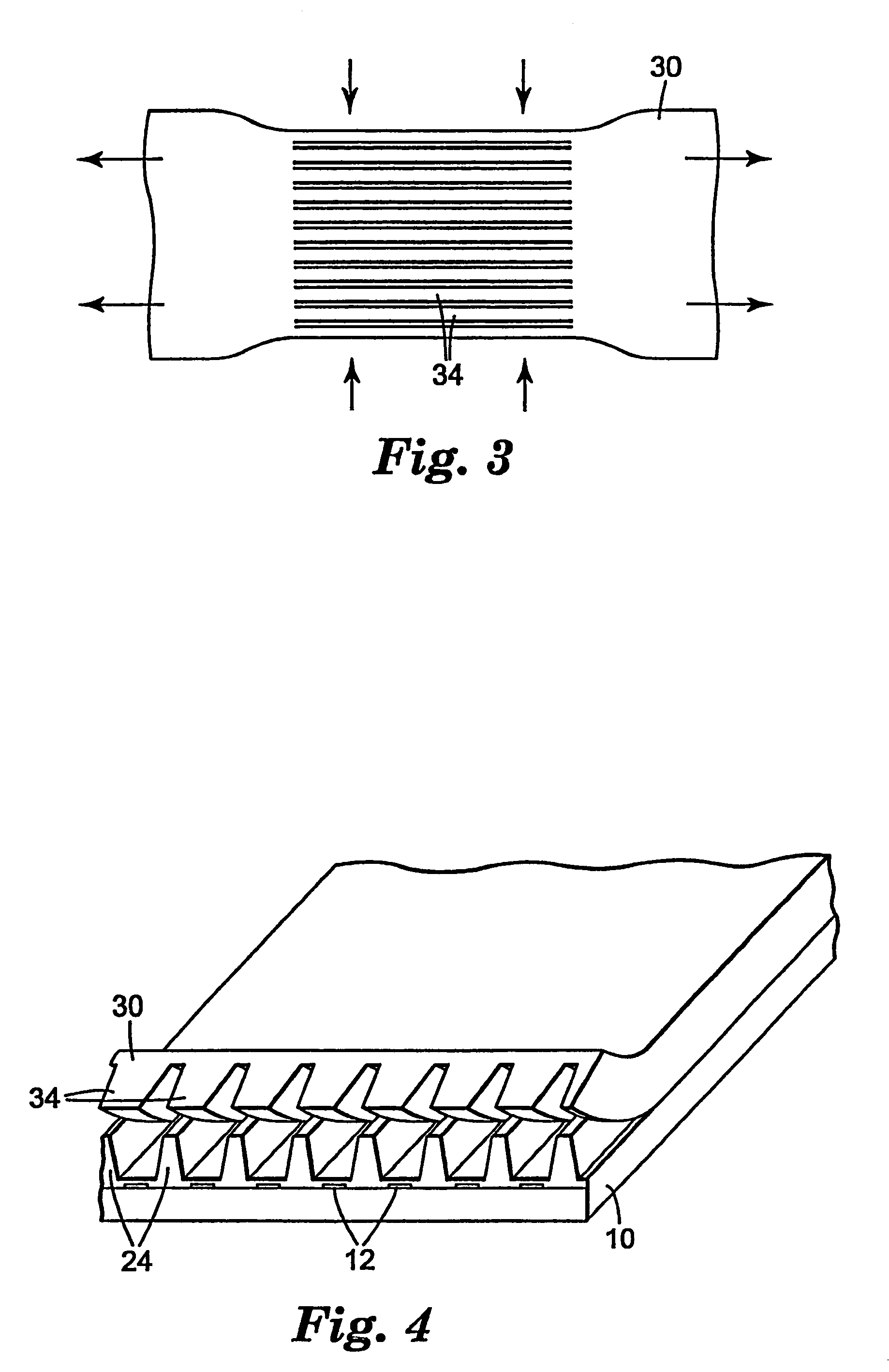
[0083]In the examples which follow, a jig was built to stretch a sheet of a polymer mold as shown in FIG. 7. To stretch a sheet of a polymer mold, S, the sheet was gripped at points A and B. Lateral force (in the plane of the mold) was then applied by turning a fine thread screw, C. The jig was designed to fit under a toolmaker microscope to observe the pattern of the polymer tool while stretching. Polymer mold pitch measurements were taken at various strain levels. Free-state pitch measurements were made before and after stretching to determine whether the levels of strain applied had caused plastic or elastic deformation. The polymer molds were about 2.5 cm wide and about 15 cm long.

example 1

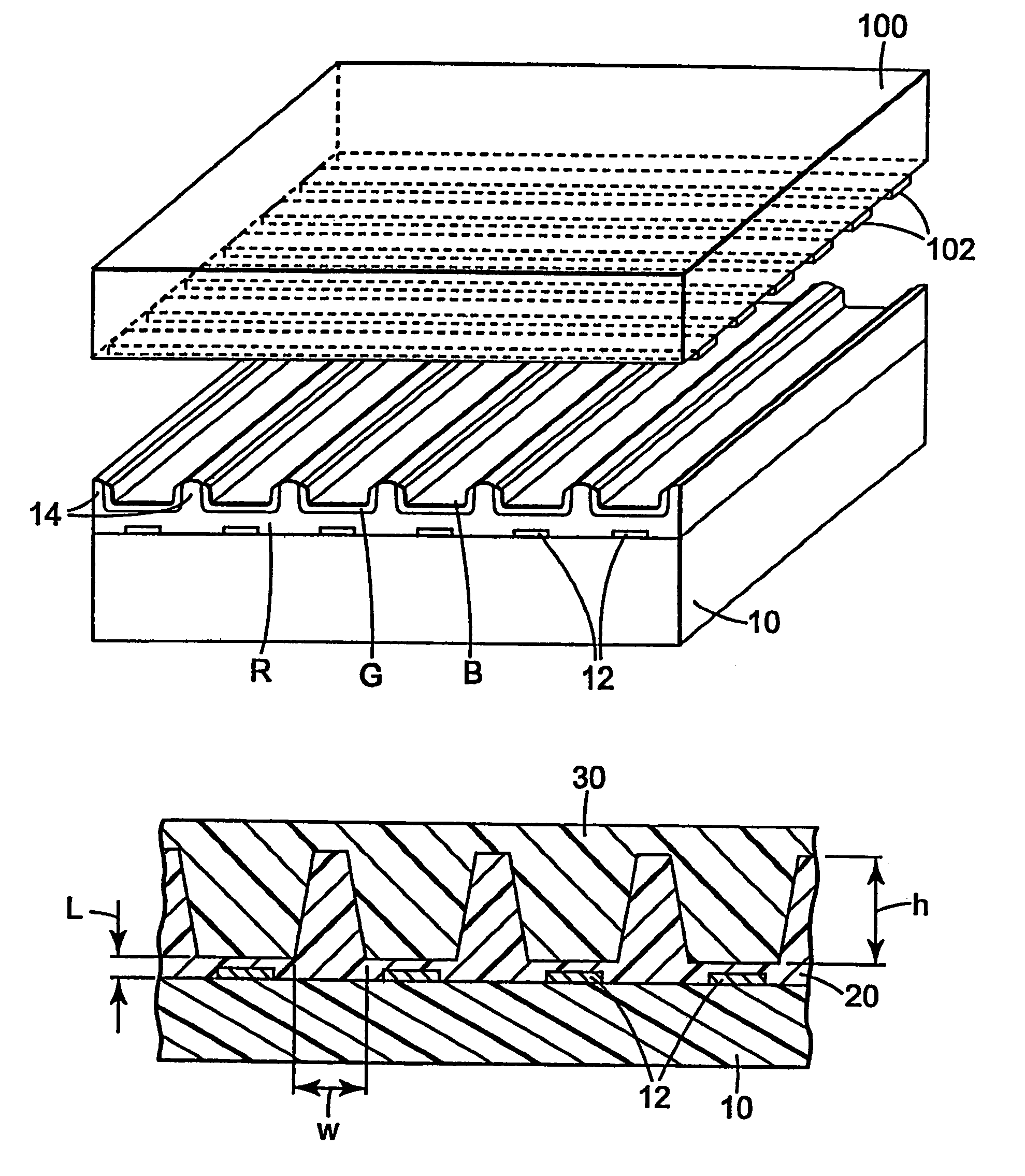
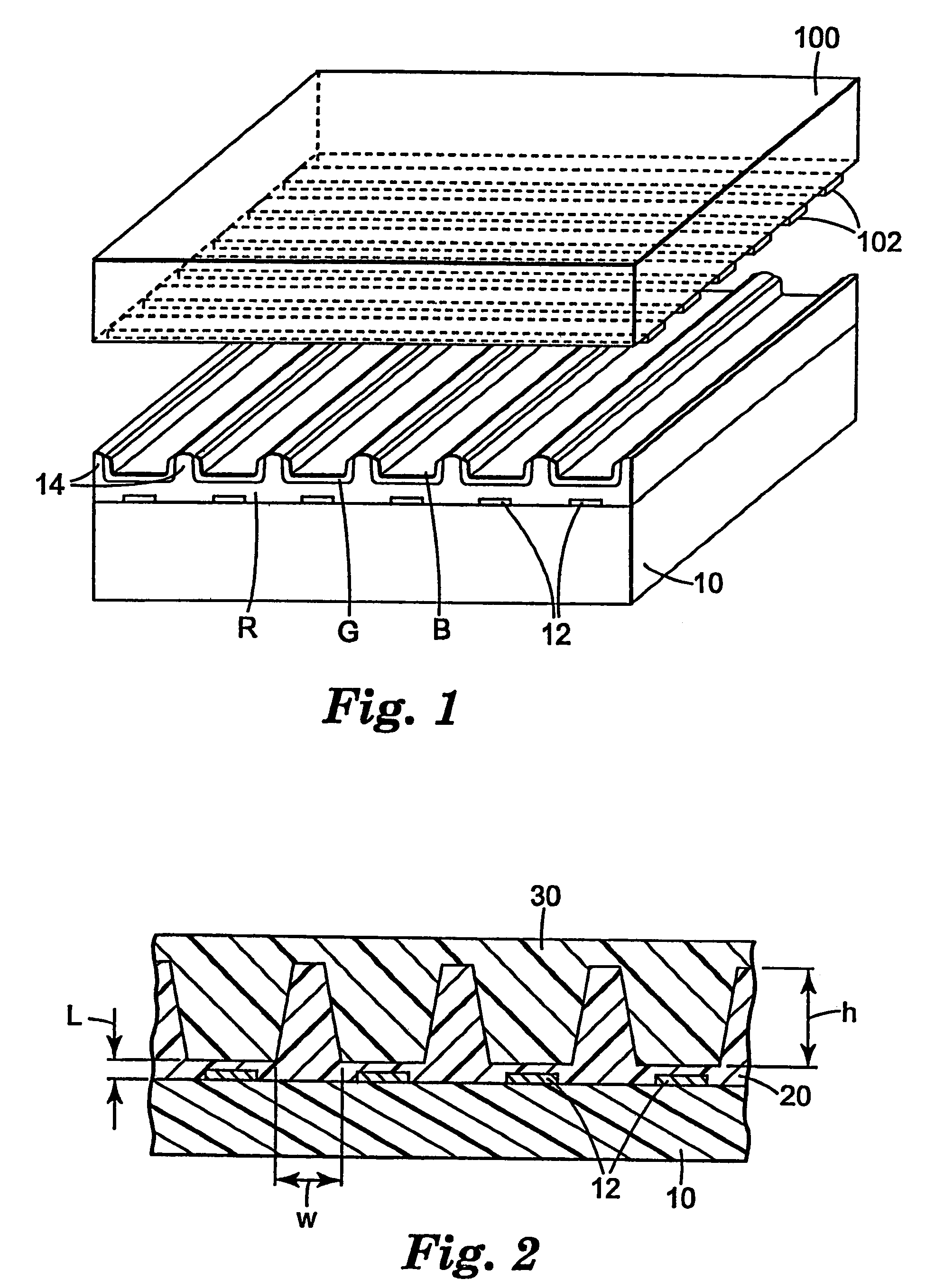
[0084]A polymer mold with V-groove microstructures was used. The polymer mold was a flat PET film onto which an acrylate material was cast and cured to form V-groove microstructures. The PET film was nominally 127 μm thick and the microstructure bearing acrylate layer was about 27 to 30 μm thick. In the free state, the V-groove structures were measured to be 49.556 μm apart from peak to peak.

[0085]As described above, the polymer mold was secured onto the jig to stretch in a direction parallel to the V-grooves. The V-groove spacing, or pitch, was measured at various levels of strain by visual inspection under a toolmaker microscope at 200× magnification. The results are summarized in Table 1. Loading conditions were indicated by the number of turns of screw C.

[0086]

TABLE 1Loading conditionPitch (μm)free state49.556pre-load (0 turns)49.5300.2549.5200.5049.5100.7549.5001.0049.4831.2549.4701.5049.463post-load (0 turns)49.530

[0087]The spacing of the microstructured grooves was affected b...

example 2

[0088]The same procedure as in Example 1 was repeated for a polymer mold having a different construction and a different pattern. In this example, the mold had rectangular channels and was a monolithic structure made entirely of polycarbonate, one surface of which was smooth and the other surface of which had the rectangular channels. The entire mold was 550 μm thick and the channels were 198 μm deep. The channels were nominally 120 μm in width and were spaced 219.94 μm apart. S strain was applied parallel to the channels in the plane of the polymer tool. The pitch measurements are summarized in Table 2.

[0089]

TABLE 2Strain (%)Pitch (μm)pre-load (0%)219.870.161219.740.342219.590.491219.45post-load (0%)219.87

[0090]Similarly to Example 1, fine control of the feature pitch spacing was demonstrated by controlled stretching of the polymer mold. Again, as much as 1900 ppm of shrinkage in the pitch of the channels was obtained by elastically stretching the mold. Furthermore, the pitch of th...


PUM

PropertyMeasurementUnit
heightaaaaaaaaaa
temperatureaaaaaaaaaa

Abstract

A method for molding and aligning microstructures on a patterned substrate using a microstructured mold. A slurry containing a mixture of a ceramic powder and a curable fugitive binder is placed between the microstructure of a stretchable mold and a patterned substrate. The mold can be stretched to align the microstructure of the mold with a predetermined portion of the patterned substrate. The slurry is hardened between the mold and the substrate. The mold is then removed to leave microstructures adhered to the substrate and aligned with the pattern of the substrate. The microstructures can be thermally heated to remove the binder and optimally fired to sinter the ceramic powder.

Description

RELATED U.S. APPLICATIONS[0001]This application is a continuation of U.S. patent application Ser. No. 10 / 626,285 filed Jul. 24, 2003, now U.S. Pat. No. 6,802,754; which is a continuation of U.S. patent application Ser. No. 09 / 972,655 filed Oct. 5, 2001, now U.S. Pat. No. 6,616,887; which is a continuation of U.S. patent application Ser. No. 09 / 779,207 filed Feb. 8, 2001, now U.S. Pat. No. 6,325,610; which is a division of U.S. patent application Ser. No. 09 / 219,803 filed Dec. 23, 1998, now U.S. Pat. No. 6,247,986.TECHNICAL FIELD[0002]The present invention generally relates to methods of forming and aligning structures on patterned substrates. More specifically, the present invention relates to methods of molding and aligning glass, ceramic, and / or metal structures on patterned substrates for display applications, and to displays having barrier ribs molded and aligned using a stretchable mold.BACKGROUND[0003]Advancements in display technology, including the development of plasma disp...

Claims


Application Information

Patent Timeline
Patent Type & Authority Patents(United States)
IPC IPC(8): H01J17/49H01J11/34B29C33/30B29C33/40B29C33/42H01J9/02H01J9/24H01J11/02H01L21/027
CPCB29C33/303H01J9/242H01J9/241B29C33/40B29C33/424H01J2217/49H01J2211/36H01J11/34H01J9/24
Inventor CHIU, RAYMOND C.HOOPMAN, TIMOTHY LEEHUMPAL, PAUL EDWARDKING, VINCENT WEN-SHIUANDILLON, KENNETH R.
Owner 3M INNOVATIVE PROPERTIES CO
Why Eureka
Try Eureka