Stator of an electrical machine

a stator and electrical machine technology, applied in the direction of winding insulation shape/form/construction, magnetic circuit shape/form/construction, electrical apparatus, etc., can solve the problem of eddy current induced in the stator core, and achieve the effect of facilitating the manufacturing of the core back

Inactive Publication Date: 2007-07-17
HOGANAS AB
View PDF6 Cites 30 Cited by
  • Summary
  • Abstract
  • Description
  • Claims
  • Application Information

AI Technical Summary

Benefits of technology

[0018]The sheet may include openings along a portion of its length. Thus, the openings may not have to extend all the way through the total thickness of the core back. This may facilitate the manufacturing of the core back.

Problems solved by technology

One problem with these types of stator cores is that eddy currents is induced in the stator core.

Method used


Image

  • Stator of an electrical machine
  • Stator of an electrical machine
  • Stator of an electrical machine

Examples


Embodiment Construction

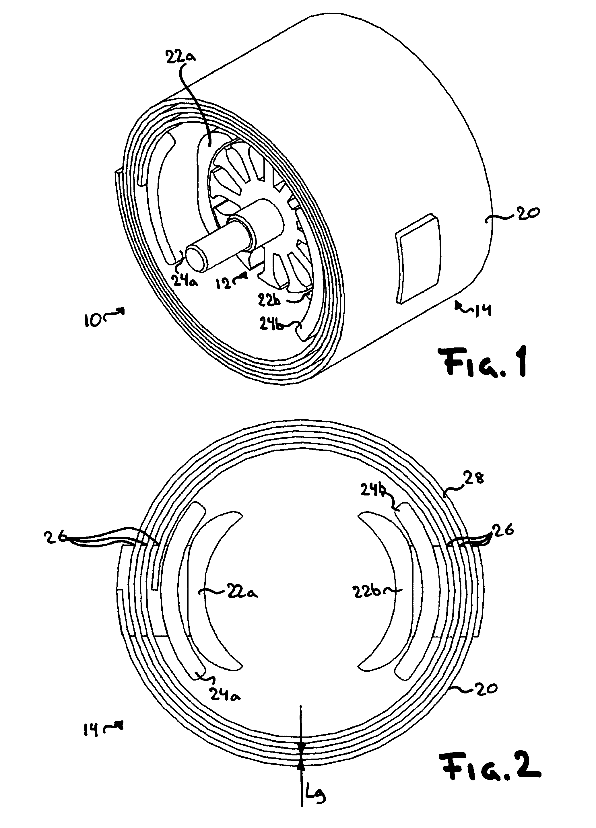
[0037]In FIG. 1 there is shown an electrical machine 10 comprising a rotor 12, a stator 14.

[0038]The rotor 12 may be a conventional rotor. Thus, the rotor may be a conventional permanent magnet rotor, a conventional synchronous rotor, a conventional asynchronous rotor, a conventional Switched Reluctance rotor (SR-rotor), etc., but may also be a rotor of a construction similar to the construction of stator 14 according to the invention. Note, that the windings of the rotor is not shown in FIG. 1.

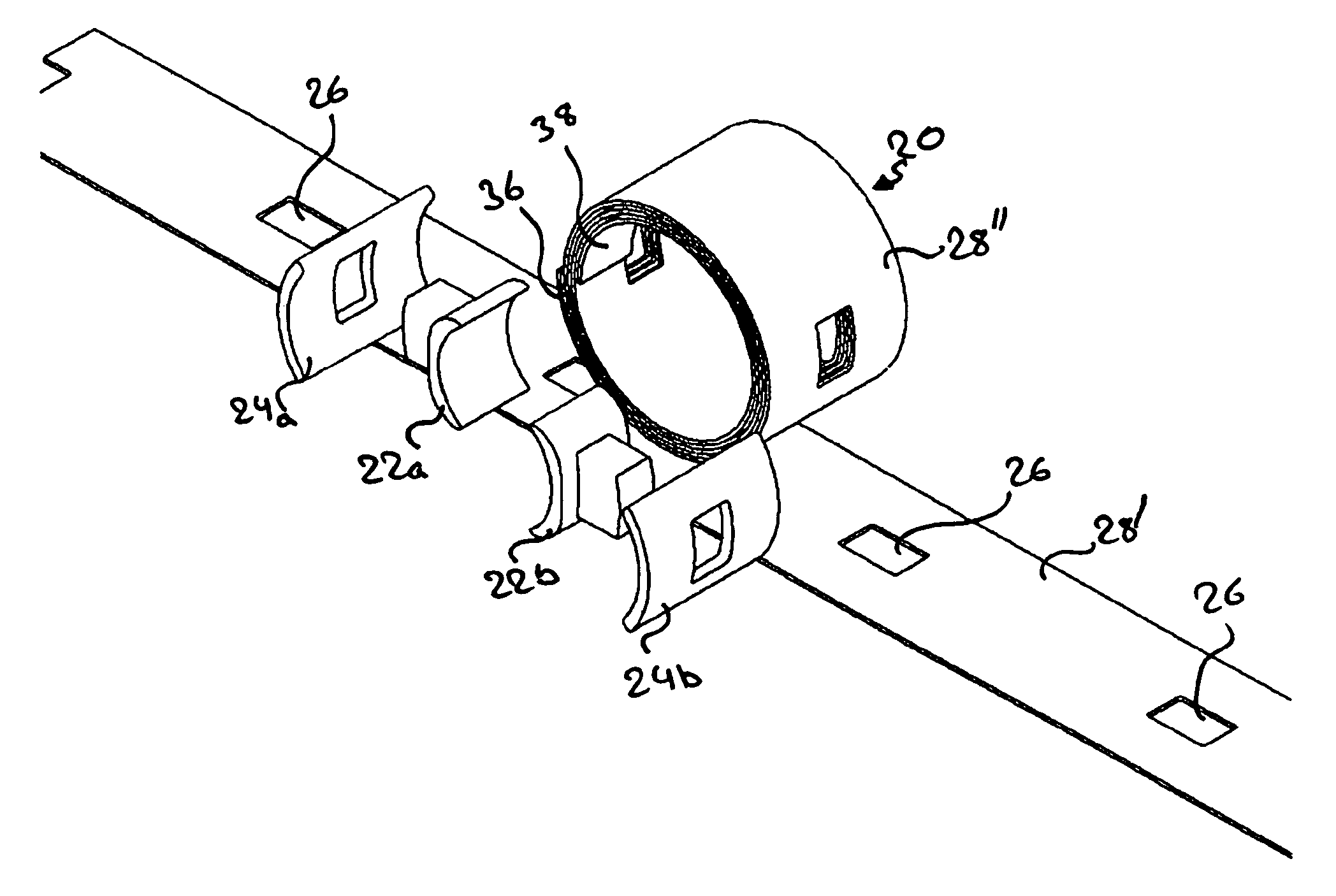
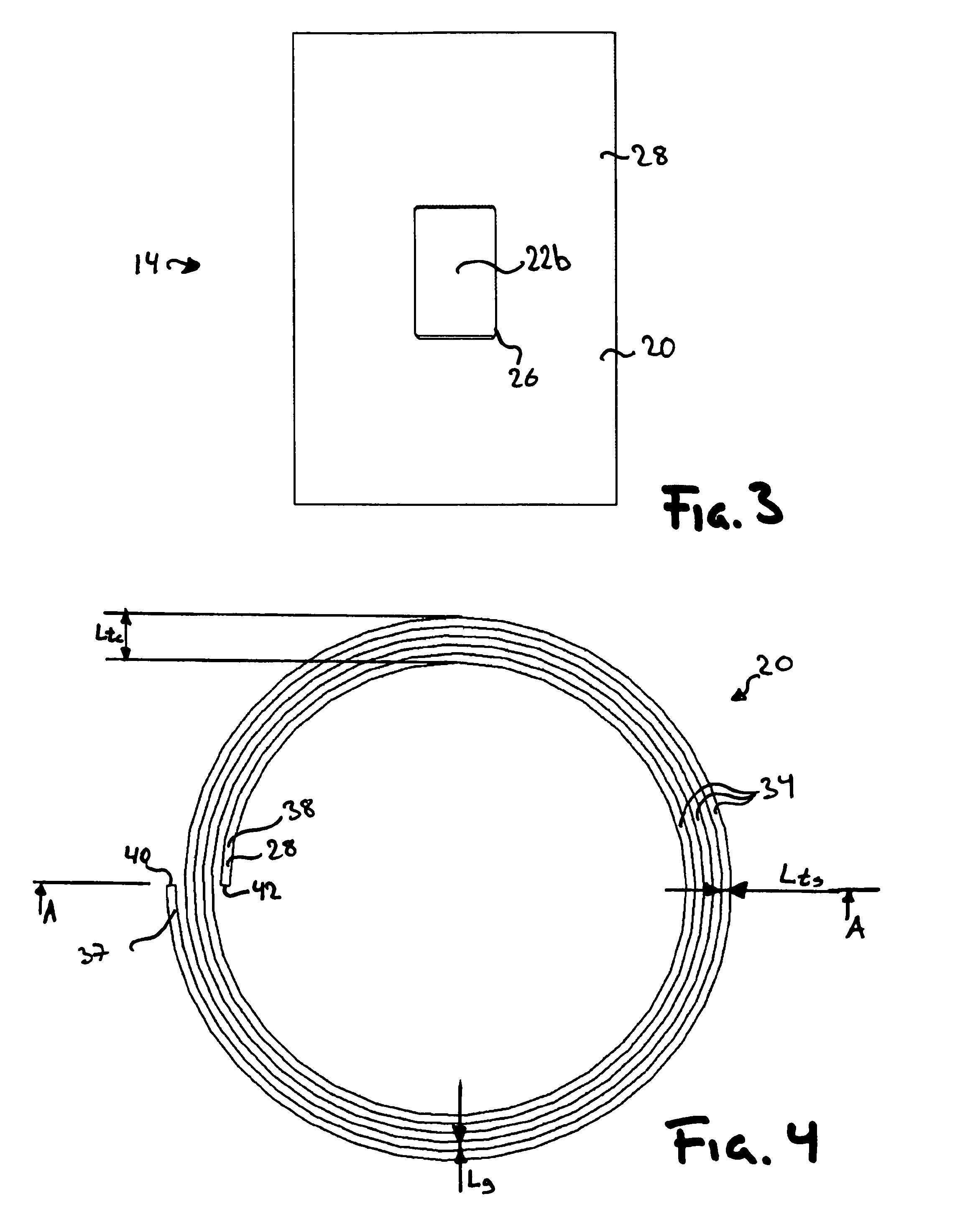
[0039]In FIG. 1–3, one embodiment of the invention is shown schematically. The stator of this embodiment comprises a core back 20, two teeth 22a–b, and coils 24a–b.

[0040]The teeth 22a–b are separate components attached to the core back 20. In the present embodiment the teeth 22a–b are attached to the core back20 by positioning the teeth 22a–b in openings 26 arranged in the core back 20. The teeth may then be force fit in the openings 26, glued, welded, or soldered to the core back.

[0041]The ...


PUM


Abstract

A stator core for an electrical machine and a method for producing the same. Said stator core comprising a core back and a plurality of teeth arranged circumferentially at the core back and extending radially there from. The core back being made of at least one sheet of electrically insulated soft magnetic material arranged as a spiral. Said method comprising the acts of winding a sheet of electrically insulated soft magnetic material into a spiral in order to form a core back and attaching a plurality of teeth to the core back so that the teeth are circumferentially separated and extends radially from the core back.

Description

[0001]The benefit is claimed under 35 U.S.C. § 119(a)–(d) of Swedish Application No. 0300799-4 filed Mar. 24, 2003, and under 35 U.S.C. § 119(e) of U.S. Provisional Application No. 60 / 473,195 filed May 27, 2003.TECHNICAL FIELD OF THE INVENTION [0002]The present invention is generally related to electrical machines and in particular to a stator and the core back of a stator of an electrical machine.BACKGROUND OF THE INVENTION [0003]The stator of electrical machines generally comprises teeth and a core back. The function of the teeth is to lead magnetic flux induced in the teeth by a coil arranged round the teeth and, thus, the teeth increases the efficiency of the interaction between the stator and a rotor, in respect of a stator having no teeth. The core back is arranged to magnetically connect the teeth to each other in order to provide a flux feedback loop having low reluctance, i.e. it may be seen as closing the magnetic circuit generating flux for interaction with a rotor.[0004]...

Claims


Application Information

Patent Timeline
Patent Type & Authority Patents(United States)
IPC IPC(8): H02K1/00H02K1/14
CPCH02K1/148H02K1/02H02K1/187H02K3/34
Inventor JACK, ALAN
Owner HOGANAS AB
Why Eureka
Try Eureka