Connector with two piece shells

a technology of connecting shells and shells, applied in the direction of coupling device connections, coupling protective earth/shielding arrangements, electrical devices, etc., can solve the problem of inclination to generate emi problems, and achieve the effect of excellent shielding function

Inactive Publication Date: 2010-11-23
CHENG UEI PRECISION IND CO LTD
View PDF5 Cites 7 Cited by
  • Summary
  • Abstract
  • Description
  • Claims
  • Application Information

AI Technical Summary

Benefits of technology

[0005]An object of the present invention is to provide a connector having a shield with excellent shielding function. The connector is adapted for electrically connecting with a complementary component inserted therein from a front direction, and includes an insulating housing having a basic body, a plurality of terminals received in the insulating housing, and a shield coupled with the insulating housing comprising an upper shell and a lower shell. The upper shell has an upper cover covering a top surface of the insulating housing and a pair of wings extending laterally from two opposite sides of the upper cover. Each of the wings has at least one slot extending along a front-to-rear direction and adjacent to the upper cover, and a plurality of positioning pegs extended downwards from a lateral edge thereof. The lower shell has a lower cover attached to a bottom surface of the basic body and two lateral plates extended upwards from two opposite sides of the lower cover and flanked to the insulating housing. Each of the lateral plates has at least one clasper which passes through the slot of the wing and extends laterally to hook a side of the slot, for buckling the upper shell with the lower shell together.
[0006]As described above, the shield is formed by the upper shell and the lower shell. The upper shell has the upper cover covering the insulating housing and wings exceeding the insulating housing. The lower shell has the lateral plates flanked to the insulating housing and buckling with the upper shell by the claspers hooking the sides of the slots formed on the wings. Furthermore, the positioning pegs are arranged at the sides of the wings. Such structure of the shield is capable of completely coating the insulating housing, without punching openings on the portion attached to the insulating housing for achieving supporting and positioning function. Therefore, the shield is preferable to prevent the connector from EMI problem.

Problems solved by technology

However, since the shield 8 made of metal plate is punched with a plurality of openings for forming the supporting slices 81 and the positioning pegs 82, it is inclined to generate EMI problem because the shield 8 is unable to shield the insulating housing 6 completely.

Method used


Image

  • Connector with two piece shells
  • Connector with two piece shells
  • Connector with two piece shells

Examples


Embodiment Construction

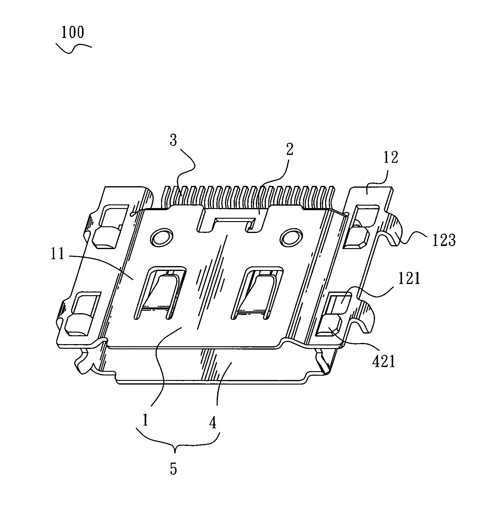
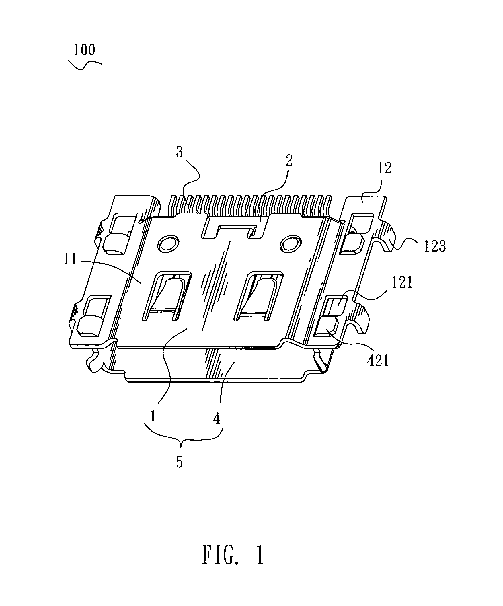
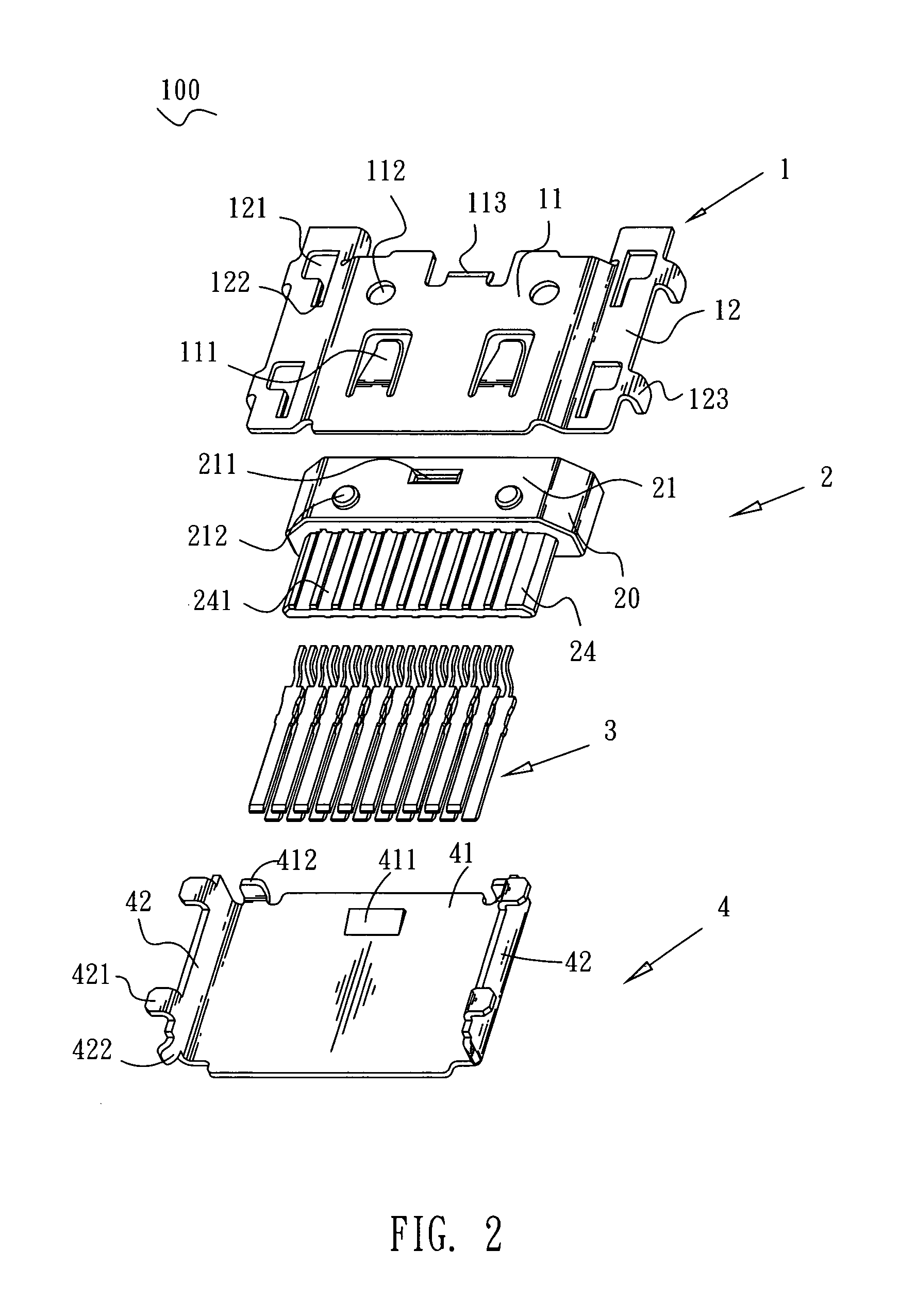
[0017]With reference to FIGS. 1-3, a connector 100 of the first embodiment mounted on a printed circuit board (PCB, not shown) includes an insulating housing 2, a plurality of terminals 3 received in the insulating housing 2 and a shield 5 coupled with the insulating housing 2. The insulating housing 2 has a substantially rectangular basic body 20. The basic body 20 defines a top surface 21, a bottom surface 22, and a rear surface 23. The top surface 21 has a restraining slot 211 extending leftwards and rightwards at a substantially middle portion thereof along a left-to-right direction, adjacent to the rear surface 23, and two circle protrusions 212 disposed at two ends thereof along the left-to-right direction, away from the rear surface 23. The bottom surface 22 has a buckling groove 221 extending frontward and rearwards at middle thereof and passing through a front thereof, and a wedge-shaped stopper 222 located at a rear end of the buckling groove 221. The rear surface 23 is re...


PUM


Abstract

A connector connected with a complementary component inserted therein from a front direction includes an insulating housing and a shield coupled with the insulating housing comprising an upper shell and a lower shell. The upper shell has an upper cover covering a top surface of the insulating housing and a pair of wings extending laterally from two opposite sides of the upper cover. The wing has a slot extending along a front-to-rear direction, and a plurality of positioning pegs extended downwards from a lateral edge thereof. The lower shell has a lower cover and two lateral plates bent upwards from two opposite sides of the lower cover and flanked to the insulating housing. Each of the lateral plates has a clasper which passes through the slot of the wing and extends laterally to hook a side of the slot, for buckling the upper shell with the lower shell together.

Description

BACKGROUND OF THE INVENTION[0001]1. Field of the Invention[0002]The present invention generally relates to a connector, and more particularly to a connector having a shield adapted for preventing electro magnetic interference.[0003]2. The Related Art[0004]A connector mounted to an electrical device for transmitting signal is required to equipped with a shield for preventing electro magnetic interference (EMI). FIG. 9 is a perspective view illustrating a connector with shielding function in prior art. The connector 200 generally involves an insulating housing 6, a plurality of terminals 7 mounted in the insulating housing 6 and a shield 8 coupled with the insulating housing 6. The shield 8 is formed integrally to enclose the insulating housing 6. A stopping portion 61, which is extended outwards and bent frontward from a rear end of each of two lateral sides of the insulating housing 6, is positioned outside the shield 8 when the shield 8 is assembled to the insulating housing 6, for...

Claims


Application Information

Patent Timeline
Patent Type & Authority Patents(United States)
IPC IPC(8): H01R13/648
CPCH01R13/65802H01R13/502H01R13/6594H01R13/6582H01R13/658
Inventor YANG, CHIH-LINGHO, HSIN-TSUNG
Owner CHENG UEI PRECISION IND CO LTD
Why Eureka
Try Eureka