[0029] The following are specific embodiments of the invention in conjunction with the accompanying drawings to further describe the technical solutions of the invention, but the invention is not limited to these embodiments.
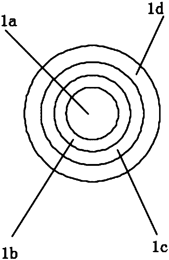
[0030] Such as figure 1 As shown, the heating wire with shielding function includes an aluminum wire 1a, a Teflon layer 1b, a copper wire layer 1c and an insulating layer 1d arranged from the inside to the outside. The copper wire layer 1c has a spiral structure and is wound around On the Teflon layer 1b, the thickness of the Teflon layer 1b is smaller than the thickness of the insulating layer 1d.
[0031] The insulating layer 1d is injection-molded and the copper wire layer 1c is embedded.
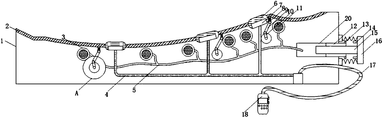
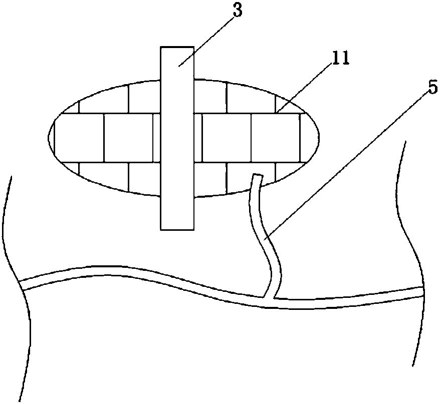
[0032] Such as Figure 1-5 As shown, the heating pad includes a heating pad 1. A heating wire with shielding function is arranged in the bottom of the heating pad 1. The top of the heating pad 1 is bonded with a glue 2, and the glue 2 is provided with small holes. The heating pad 1 A small hole is opened on the right side of the small hole, and the control line 17 passes through the inside of the small hole. The two ends of the small hole are glued with the Chinese medicine pack 6. The setting of the Chinese medicine pack 6 makes the Chinese medicine pack 6 volatilize better by heating during the heating process. Perform physical therapy on various parts of the patient. The bottom of the traditional Chinese medicine package 6 is glued with a heater 7, and the inside of the heater 7 is installed with a wire 4 through screws. The other end of the wire 4 is installed inside the thermostat through screws. The control wire 17 is welded and installed inside the control wire 17 and the other end of the control wire 17 is welded and installed inside the controller 18. One side of the controller 18 is equipped with a display screen, and one side of the controller 18 is equipped with a control button, and the heating pad 1 A heat dissipation hole 3 is opened on one side. Through the arrangement of the heat dissipation hole 3, the airbag 11, the inflator 12, the button 16, etc., after the personnel use the heating pad 1, the heat dissipation hole 3 can be opened by releasing the air inside the airbag 11. , So that the device can quickly dissipate heat, the airbag 11 is bonded on both sides of the heat dissipation hole 3, the inside of the airbag 11 is bonded with a rubber tube 5, the other end of the rubber tube 5 is bonded to the inside of the plastic shell 20, and the other end of the plastic shell 20 One end is fixed with an inflatable cylinder 12 by screws, two sides of the inflatable cylinder 12 are fixed with rivets 13 with clamping holes 13, and a clamping column 14 is welded on one side of the button 16. The cross-sectional area of the clamping column 14 and the cross-sectional area of the clamping hole 13 Equal, the center of the clamping column 14 and the center of the clamping hole 13 are on the same axis. The inflatable cylinder 12 is fixed at both ends of the opening by rivets. The opening is opened on one side of the heating pad 1. The inflatable cylinder 1 is embedded with a working rod 15 , The other end of the working rod 15 is fixed with a button 16 by screws, one side of the button 16 is welded with a spring, the other end of the spring is welded with a spring fixing block, and the other side of the spring fixing block is fixed to one side of the heating pad 1 by screws , The inner wall of the heating pad 1 is fixed with a closed cylinder 19 by rivets, one side of the closed cylinder 19 is provided with a small hole, the output end of the micro motor passes through the inside of the small hole, and the inside of the closed cylinder 19 is installed with a micro motor by screws , The output end of the micro motor is connected with a roller through a coupling, the other side of the roller is welded with a connecting rod, the other end of the connecting rod is sleeved with a rotating rod 10, and the other end of the rotating rod 10 is connected with a linkage rod 9 through a shaft, The other end of the linkage rod 9 is hinged with a massage rod 8. The massage rod 8, a micro motor, a linkage rod 9, a rotating rod 10 and other structures are set up so that personnel can control the motor movement through the controller to control the waist, shoulder spine, etc. Massage physiotherapy on the part, which has powerful functions and good physiotherapy effects. The middle part of the massage rod 8 is welded with a spring, the outer side of the Chinese medicine package 6 is bonded with a rubber sleeve, and the other end of the massage rod 8 is bonded to one side of the gel 2 .
[0033] In this embodiment, when working, the person lies on the humanoid gel 2 and turns on the power to energize the interior of the heating pad 1, and then the person turns on the power of the controller 18. There are a total of 8 function buttons on the controller 18, namely: spine , Waist and shoulder, heating, cooling, power supply, timing, screen lock and shielding button. The shielding button is installed on the side of the controller 18, and the other buttons are installed on the front of the controller 18. When the person presses the heating button, the temperature controller passes through the wire The heater 7 is energized to work to heat the whole body of the patient. Under the action of the traditional Chinese medicine package 6, the patient is treated with physiotherapy. When the spine button is pressed, the micromotor under the spine starts to rotate, and the rotating rod 10 rotates at this time to drive The linkage rod 9 makes a circular motion. The other end of the linkage rod 9 drives the massage rod 8 to move to massage the person’s spine. When the waist and shoulder button is pressed, the massage rod 8 massages the person’s waist and shoulders at the same time. After the physical therapy is over, The person turns off the power, and then pulls the clamping column 14 out of the clamping hole 13 to move the working rod 15 to the right. At this time, the air inside the airbag 11 enters the plastic shell 20 through the rubber tube, and then flows out from the inflator 12. When the heat dissipation hole 3 is opened, the internal heater 7 cools down quickly. The next time the person uses the button 16 to inflate the airbag 11, since the airbag 11 is a small airbag, a one-time press can fill the air inside, and then it will be stuck. The post 14 is clamped in the clamping hole 13 to block the heat dissipation hole 3.
[0034] The controller 18 in this embodiment is in the prior art, and its structure and specific circuit are not further described in this application.
[0035] Also, such as Figure 5 As shown, a hard support plate 21 is provided on the inner bottom of the heating pad 1, a number of arc-shaped protrusions 22 are provided on the upper surface of the hard support plate 21, and an upwardly convex ring shape is provided on the periphery of the hard support plate 21 The convex portion 23 is provided with an annular groove 231 on the inner side of the annular convex portion 23, and a flame-retardant sheet 24 is also provided on the upper surface of the hard support plate 21. The flame-retardant sheet 24 is located above the arc-shaped protrusion 22 and on the flame-retardant sheet The circumferential direction of the ring 24 is provided with an annular matching convex portion 25 that is clamped in the annular groove 231. The outer diameter of the annular matching convex portion 25 is larger than the diameter of the opening of the annular groove 23.
[0036] Secondly, a number of arc-shaped recesses 26 corresponding to the arc-shaped protrusions 22 are provided on the lower surface of the flame-retardant sheet 24 one by one.
[0037] A ventilation tube 27 with an inner end extending between the hard support plate 21 and the flame-retardant sheet 24 is penetrated in the annular convex portion 23, and the ventilation tube 27 is connected to an air source.
[0038] The flame retardant sheet 24 is located under the wire 4.
[0039] The specific embodiments described herein are merely examples to illustrate the spirit of the present invention. Those skilled in the art to which the present invention pertains can make various modifications or additions to the specific embodiments described or use similar alternatives, but they will not deviate from the spirit of the present invention or exceed the definition of the appended claims. Range.