Direct current power transmission and distribution system

a technology of direct current and power transmission, applied in the direction of electric power transfer ac network, ac network voltage adjustment, two-wire dc circuit, etc., can solve the problems of reducing the load carrying capacity of the cable, reducing the capacity of the load carrying cable, and requiring the transportation of high-power equipmen

Active Publication Date: 2010-12-14
GENERAL ELECTRIC CO
View PDF19 Cites 30 Cited by
  • Summary
  • Abstract
  • Description
  • Claims
  • Application Information

AI Technical Summary

Problems solved by technology

Transportation of electrical power to oil and gas sub-sea electrical equipment often requires high power being transported over long distances.
For applications wherein bulk power is transmitted over long distances, alternating current (AC) transmission provides technical challenges.
Because the cable must carry this current as well as the useful load current, this physical limitation reduces the load carrying capability of the cable.
Because capacitance is distributed along the entire length of the cable, longer lengths result in higher capacitance and higher resulting charging current.

Method used


Image

  • Direct current power transmission and distribution system
  • Direct current power transmission and distribution system
  • Direct current power transmission and distribution system

Examples


Embodiment Construction

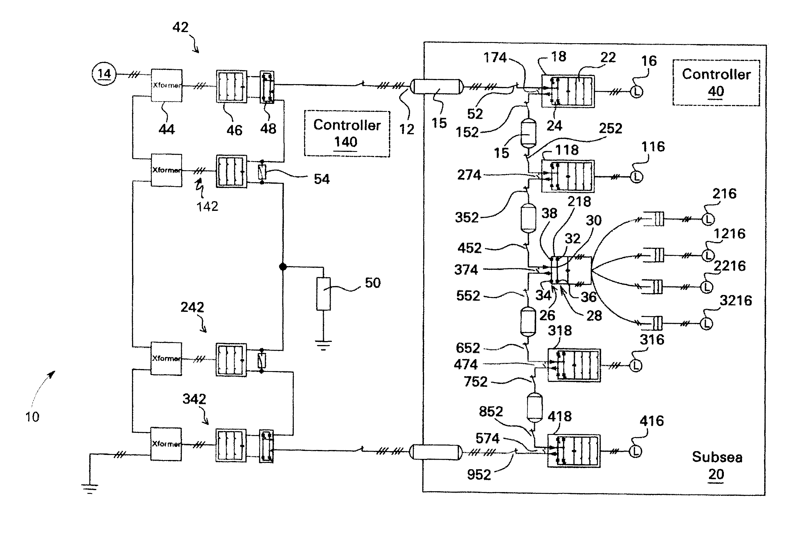
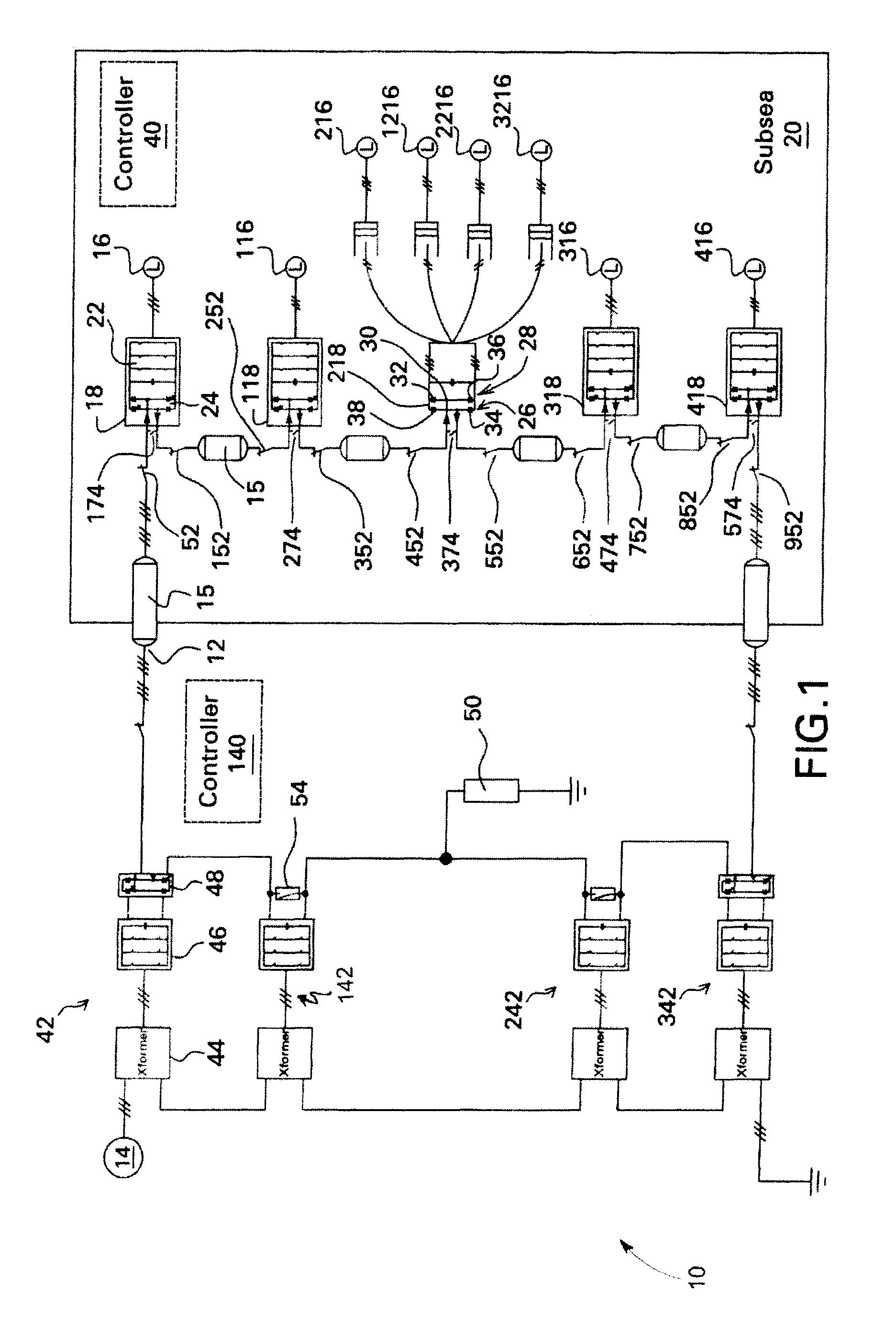
[0021]FIG. 1 is a block diagram of one embodiment wherein a direct current (DC) transmission and distribution system 10 comprises a system DC link 12 configured for carrying power from a source 14 (meaning at least one source) to a load 16 (meaning at least one load), and DC to alternating current (AC) power converter modules 18, 118, 218, 318, 418 coupled in series to system DC link 12 on a load side of the system DC link.

[0022]The embodiment of FIG. 1 is particularly useful for transmitting bulk electrical power from a source to a distant load using DC transmission wherein the DC voltage level is at least medium (for example, at least ten kilovolts). Typically the distances are greater than twenty kilometers but what is considered “distant” will vary depending upon power requirements of the load. Additionally, some applications may exist wherein the benefits of stringing load-side power conversion modules in DC are not dependent upon long distances. In sub-sea embodiments, for exa...


PUM


Abstract

A direct current (DC) transmission and distribution system includes a system DC link configured for carrying power from a source to a plurality of loads {16} and DC to alternating current (AC) power converter modules coupled in series to the system DC link on a load side of the system DC link

Description

CROSS REFERENCE TO RELATED APPLICATION[0001]This application is being filed concurrently with commonly assigned US patent application No. 11 / 608,570 which is herein incorporated by reference.BACKGROUND[0002]The subject matter disclosed herein relates generally to converter topologies useful for direct current (DC) power transmission and distribution.[0003]Transportation of electrical power to oil and gas sub-sea electrical equipment often requires high power being transported over long distances. Transmission for sub-sea equipment is used to supply the power from the onshore utility to the point where the power starts to be distributed among individual loads. At this point, a step down transformer is usually involved to bring the high voltage level of the transmission stage to a lower voltage level for the distribution stage to individual units of the electrical equipment. The distribution distance is typically shorter than the transmission distance, and the associated power and vol...

Claims


Application Information

Patent Timeline
Patent Type & Authority Patents(United States)
IPC IPC(8): H02J3/14
CPCH02J1/06H02J3/36H02M2001/0074H02M2001/008Y02E60/60H02M1/0074H02M1/008
Inventor DATTA, RAJIBSIHLER, CHRISTOF MARTINZHANG, RICHARD S.
Owner GENERAL ELECTRIC CO
Why Eureka
Try Eureka