Window covering switchable to manual operation and electrical operation and a clutch thereof

a technology of window covering switch and clutch, which is applied in the direction of shutter/window protective device, door/window protection device, wing arrangement, etc., can solve the problems of difficult hand raising or lowering of the window covering, and the practicality of the window covering suffers, so as to improve the shortcomings

Inactive Publication Date: 2010-12-28
CHENG LI MING
View PDF13 Cites 24 Cited by
  • Summary
  • Abstract
  • Description
  • Claims
  • Application Information

AI Technical Summary

Benefits of technology

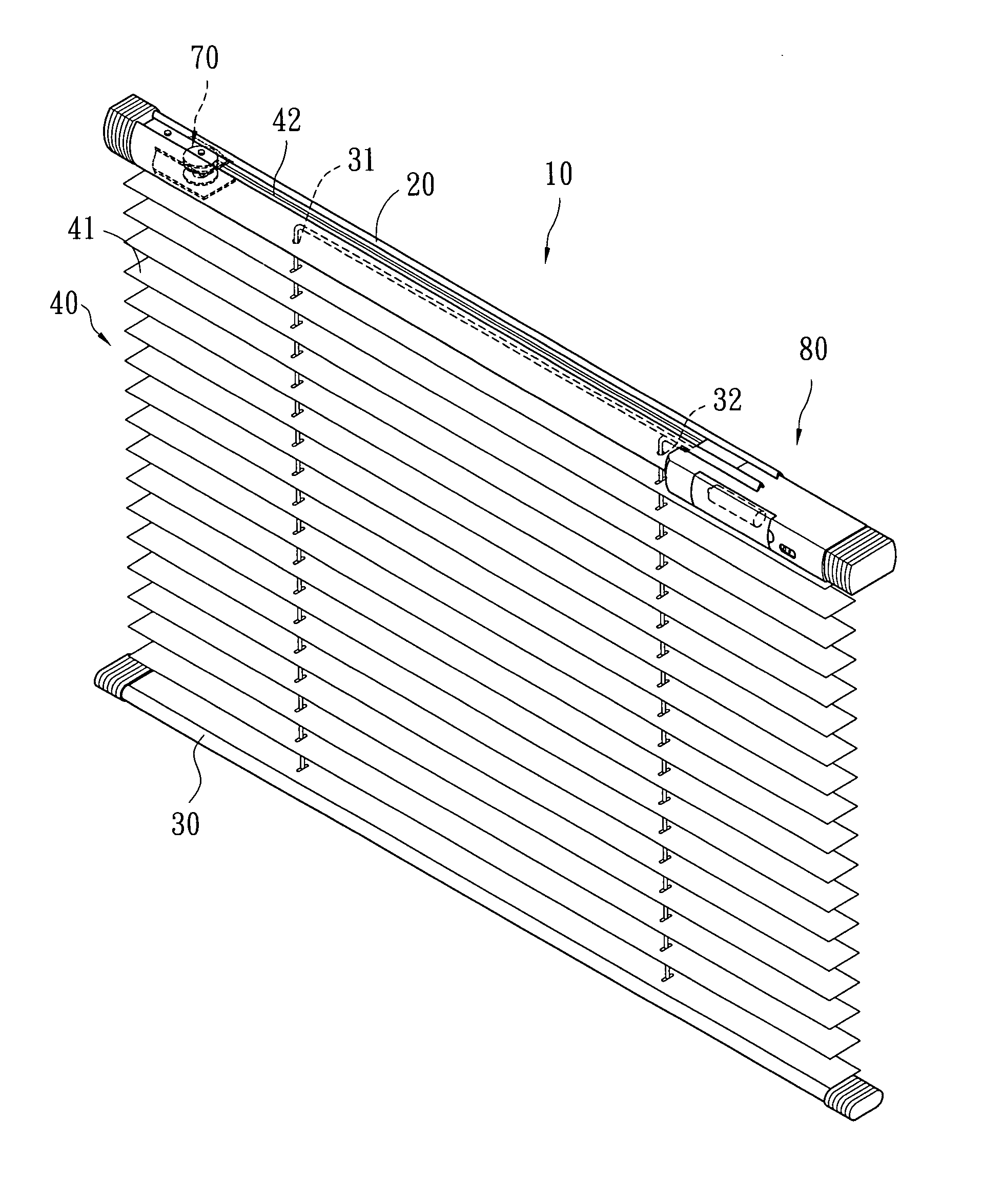
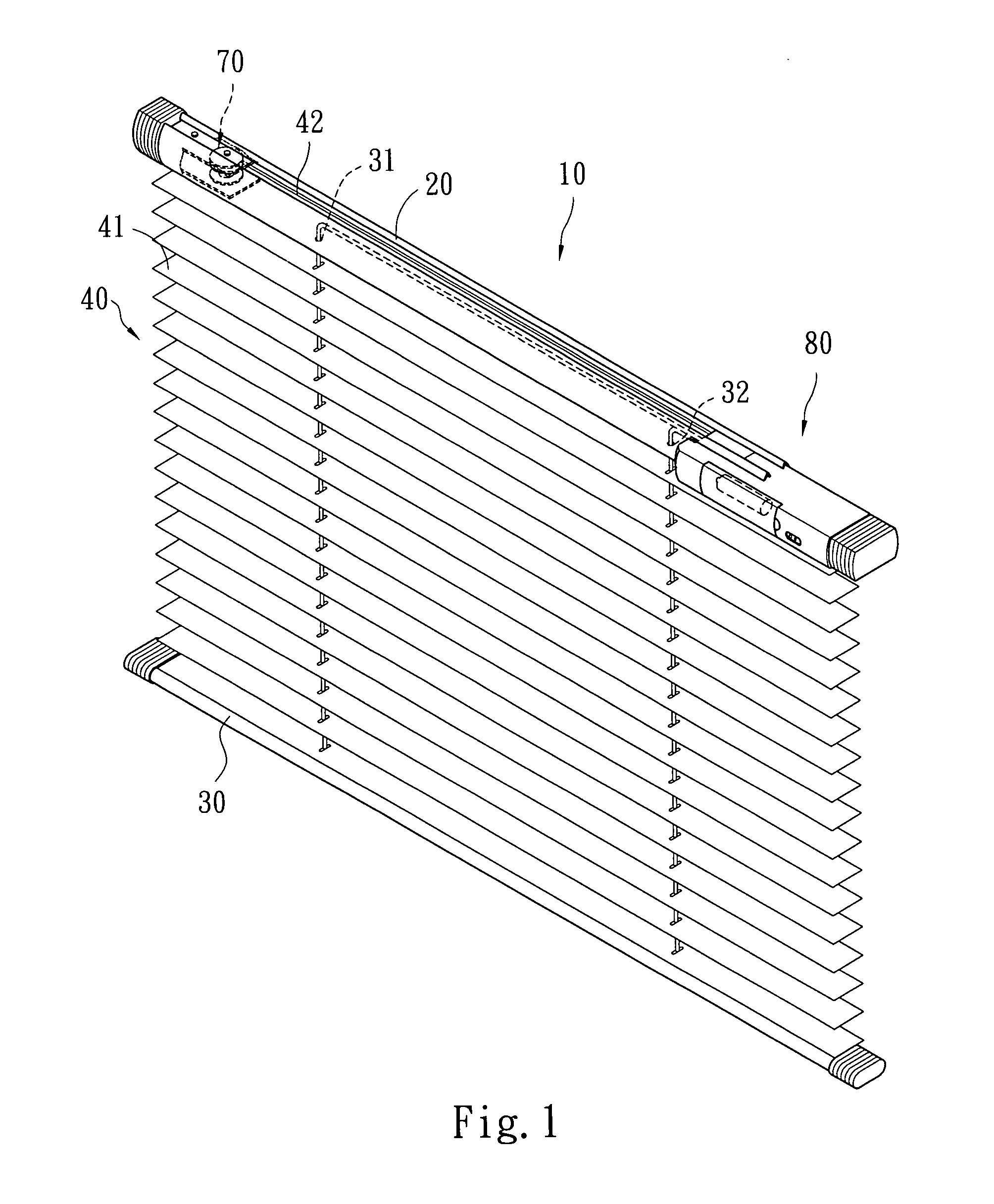
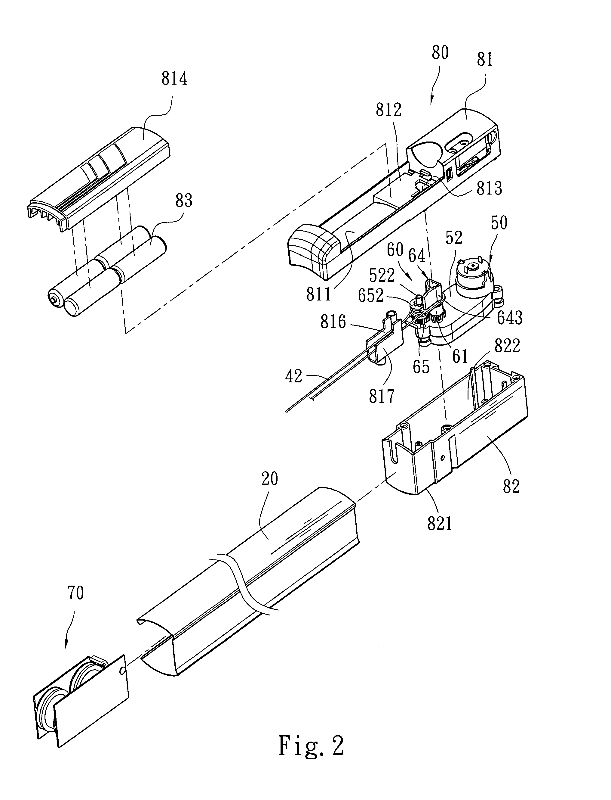
[0005]The primary object of the present invention is to provide a window covering that can be switched to manual operation and electrical operation to improve the shortcomings of the conventional electric window covering that cannot be rolled up or lowered at a desired elevation manually when electric power is not available. The invention includes an electric transmission assembly which has a control module at an upper side containing a battery. By depressing a pushbutton a driving gear in a clutch is lowered to engage with a driven gear to perform transmission synchronously to control rising up and extension of the window covering electrically. When electric power is not available the battery can be removed to move the driving gear higher to disengage with the driven gear, and the window covering can be extended or rolled up by switching to a manual operation.
[0006]Another object of the invention is to provide a clutch for electric window coverings to improve the problem of the conventional electric window covering that cannot be rolled up or extended the window covering at a desired elevation manually when the electric power is not available. The electric transmission assembly includes a gear box which has an axle connecting to the clutch. By depressing the pushbutton the driving gear in the clutch is lowered to engage with the driven gear to do transmission synchronously to control rising up and extension of the window covering electrically. When the pushbutton is released the driving gear is moved higher to disengage with the driven gear, and the window covering can be extended or rolled up by switching to the manual operation.

Problems solved by technology

While consumer's requirements may be different, safety always is an important issue.
1. When the conventional electric window covering is in a no power condition the motor and gear box are not functioning, lowering down or rising up the window covering by hands is difficult.
2. When the conventional electric window covering is in a no power condition to lower down or roll up the window covering at a desired elevation and anchored there is more difficult. As a result the practicality of the window covering suffers.

Method used


Image

  • Window covering switchable to manual operation and electrical operation and a clutch thereof
  • Window covering switchable to manual operation and electrical operation and a clutch thereof
  • Window covering switchable to manual operation and electrical operation and a clutch thereof

Examples


second embodiment

[0034]Refer to FIG. 9 for the invention. The clutch 60a has a pusher 645a which has a slanted surface 646a at one end. The pushbutton 64a has a boss 643a at an upper end thereof that has a slope 644a at one end opposing the slanted surface 646a such that the slanted surface 646a is in contact with the slope 644a to press and release the pushbutton 64a. The electric window covering 10 has a battery box 81 which has a slot 810 to allow another end of the pusher 645a to extend outside the surface of the battery box 81. When the pusher 645a is moved on surface of the battery box 81 towards one end, the slanted surface 646a presses the pushbutton 64a, and the bottom of the pushbutton 64a compresses the driving gear 61 to engage with the driven gear 65. Therefore the window covering 10 can be operated electrically. When the pusher 645a is moved towards another end the pushbutton 64a is released, and the spring 63 pushes the driving gear 61 to escape the driven gear 65 (referring to FIGS. ...

third embodiment

[0035]Refer to FIGS. 12 and 13 for the invention. The clutch 60b includes at least a driving gear 61b, a driven gear 65b and a pusher 645b. The driving gear 61b is mounted onto the axle 511. The driven gear 65b is located on the anchor shaft 522 of the gear box 52. The driven gear 65b has a pulley 652 wound by the lift cord assembly 42 so that the pulley 652 can be rotated with the driven gear 65b synchronously. The pusher 645b has one end pivotally coupled with a middle gear 68b. The electric window covering 10 has a battery box (not shown in the drawings) same as the battery box 81 shown in the embodiment depicted in FIGS. 3 and 8. The battery box has a slot (not shown in the drawings) to allow another end of the pusher 645b to extend outside the surface of the battery box. The pusher 645b can be moved towards one end, and the middle gear 68b is engaged with the driving gear 61b and the driven gear 65b at the same time to allow the electric window covering 10 to be operated electr...

fourth embodiment

[0036]Refer to FIG. 14 for a fourth embodiment in which the clutch 60c includes at least a driving gear 61c, a driven gear 65c and a pusher 645c. The driving gear 61c is mounted onto the axle 511. The pusher 645c has one end pivotally coupled with the driven gear 65c which has a pulley 652 for winding the lift cord assembly 42 such that the pulley 652 can rotate with the driven gear 65c synchronously. The electric window covering 10 has a battery box (not shown in the drawings) same as the battery box 81 shown in the embodiment depicted in FIGS. 3 and 8. The battery box has a slot to allow another end of the pusher 645c to extend outside the surface of the battery box. The pusher 645c can be moved towards one end to allow the driving gear 61c to be engaged with the driven gear 65c so that the electric window covering 10 can be operated electrically. When the pusher 645c is moved towards another end the driving gear 61c and the driven gear 65c are disengaged. Then the window covering...


PUM


Abstract

A window covering switchable to manual operation and electrical operation includes at least an upper elongated member, a lower elongated member, a shade lift cord assembly, an electric transmission assembly, a clutch and an automatic retraction means. The electric transmission assembly is coupled with the clutch through an axle of a gear box to drive a driving gear thereon to rotate. The driving gear is engaged with a driven gear pivotally coupled with the automatic retraction means to form a synchronous transmission thereby to control retraction and extension of the electric window covering. When electric power is not available manual operation may be switched through the clutch to extend or retract the window covering.

Description

FIELD OF THE INVENTION[0001]The present invention relates to a window covering switchable to manual operation and electrical operation and particularly to a window covering that has a shade assembly driven manually and electrically through a clutch.BACKGROUND OF THE INVENTION[0002]There are many types of window coverings available on the market, such as blinds, pleated shade, roman shade and the like. They mainly are installed on windows or doors in houses to block sunshine and provide decorative function. While consumer's requirements may be different, safety always is an important issue. Taking this issue into account, an electrically driven window covering usually is adopted to control rising up or lowering down of the window covering. However, the electric window covering still has problems when in use, notably:[0003]1. When the conventional electric window covering is in a no power condition the motor and gear box are not functioning, lowering down or rising up the window cover...

Claims


Application Information

Patent Timeline
Patent Type & Authority Patents(United States)
IPC IPC(8): E06B9/32
CPCE06B9/322
Inventor CHENG, LI-MING
Owner CHENG LI MING
Why Eureka
Try Eureka