Waterproof connector having movable connector member and waterproof apparatus using the same

a technology of waterproof connectors and connector parts, which is applied in the direction of coupling device connections, instruments, optical elements, etc., can solve the problems of relatively complicated operation of waterproof apparatuses, and achieve the effect of reducing or eliminating the force applied to optical fibers

Inactive Publication Date: 2010-12-28
HIROSE ELECTRIC GROUP
View PDF11 Cites 59 Cited by
  • Summary
  • Abstract
  • Description
  • Claims
  • Application Information

AI Technical Summary

Benefits of technology

[0019]According to the present invention, the waterproof connector may further include a member disposed inside the main body portion and fixed to a rigid cord member extending inside the main body portion together with an optical fiber to be connected to the ferrule. When the rigid cord member is pulled to the opposite side of the mating connector in the facing direction, the member abuts against a wall surface of the main body portion to reduce or eliminate a force applied to the optical fiber.

Problems solved by technology

As a result, an operation of the waterproof apparatus becomes relatively complicated.

Method used


Image

  • Waterproof connector having movable connector member and waterproof apparatus using the same
  • Waterproof connector having movable connector member and waterproof apparatus using the same
  • Waterproof connector having movable connector member and waterproof apparatus using the same

Examples


Embodiment Construction

[0031]Hereunder, embodiments of the present invention will be explained with reference to the accompanying drawings.

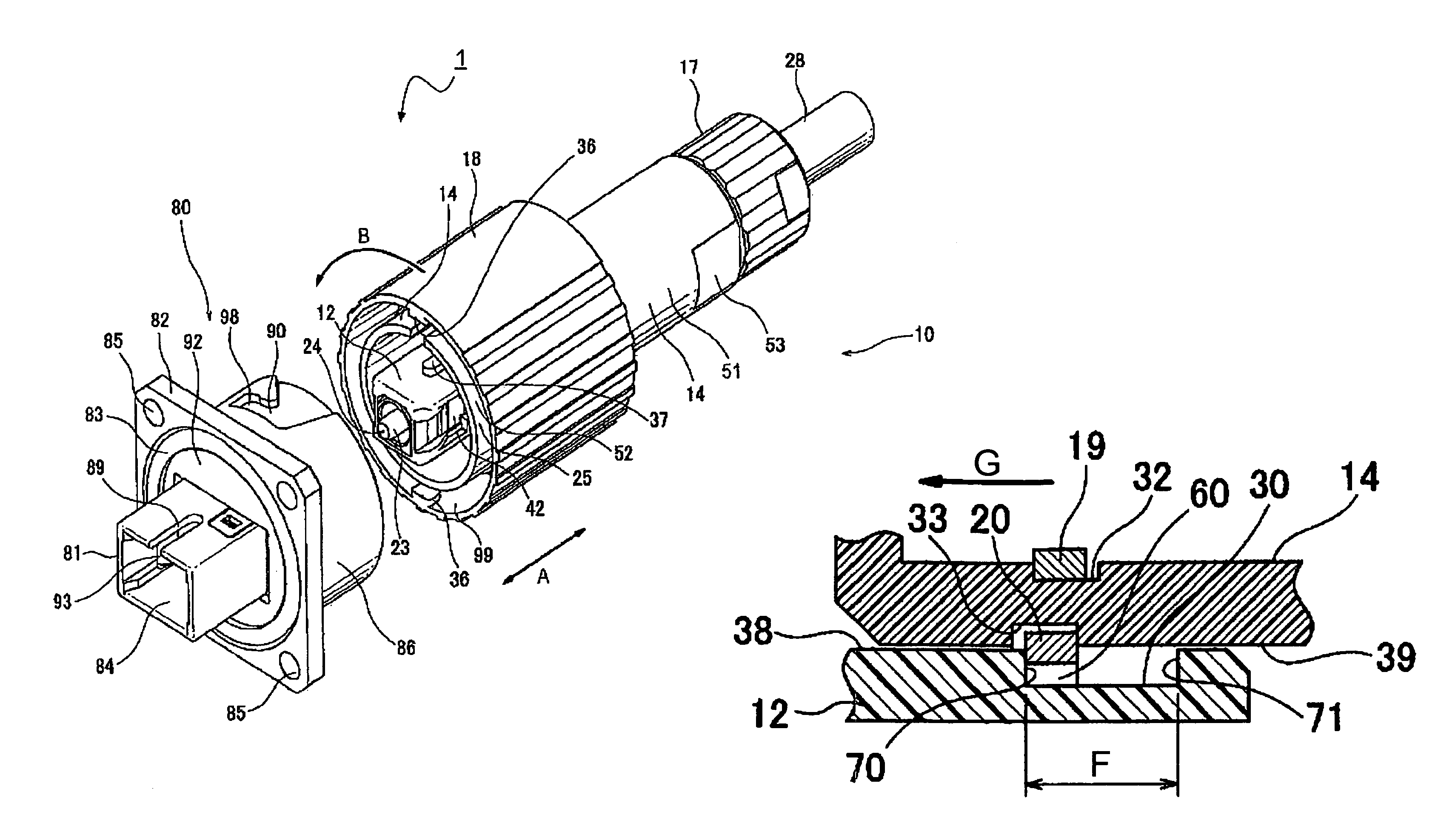
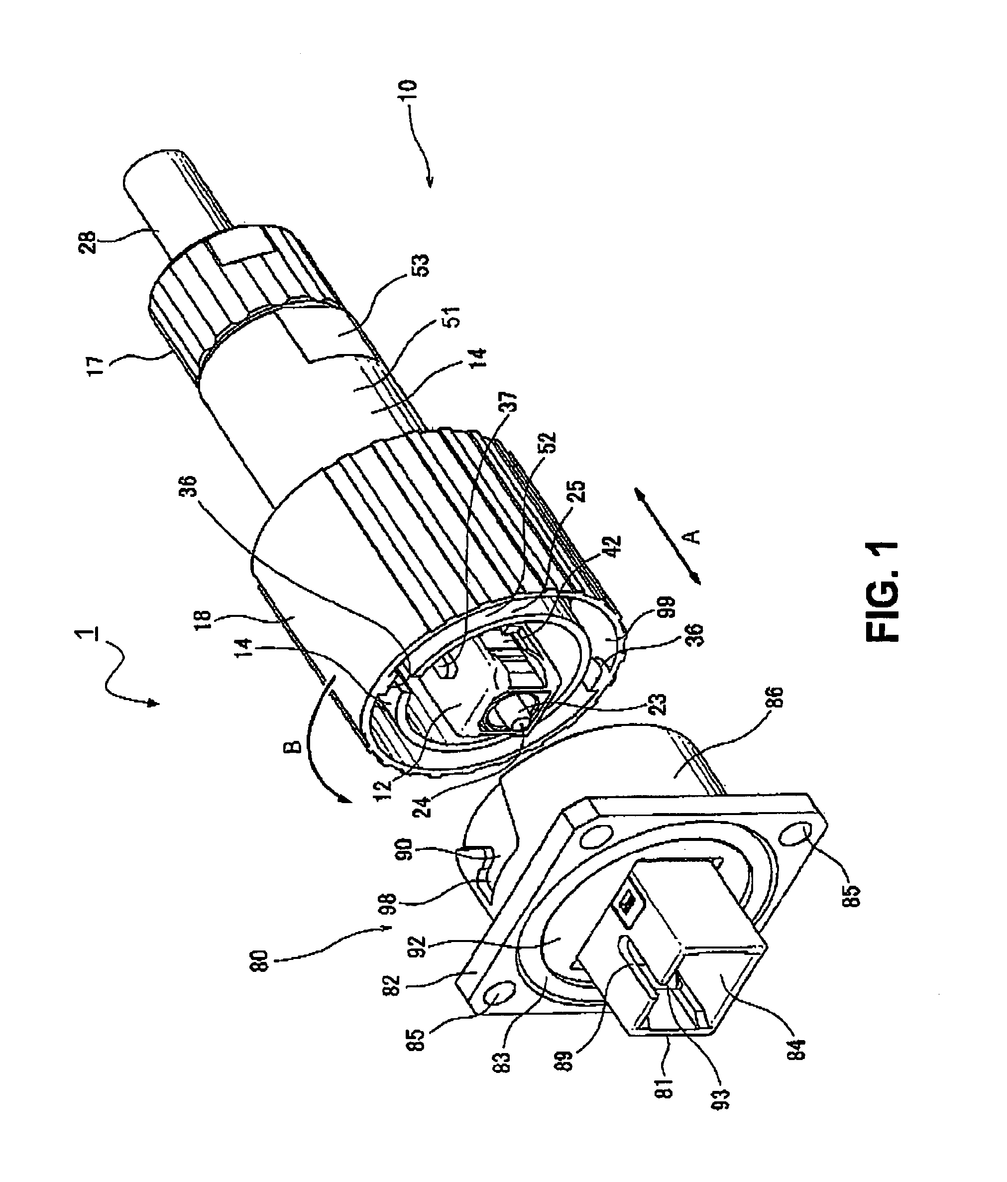
[0032]FIG. 1 is a perspective view showing a waterproof apparatus 1 according to an embodiment of the present invention. The waterproof apparatus 1 includes a waterproof connector 10 (plug connector) and a mating connector 80 (receptacle connector) to be connected to the waterproof connector 10.

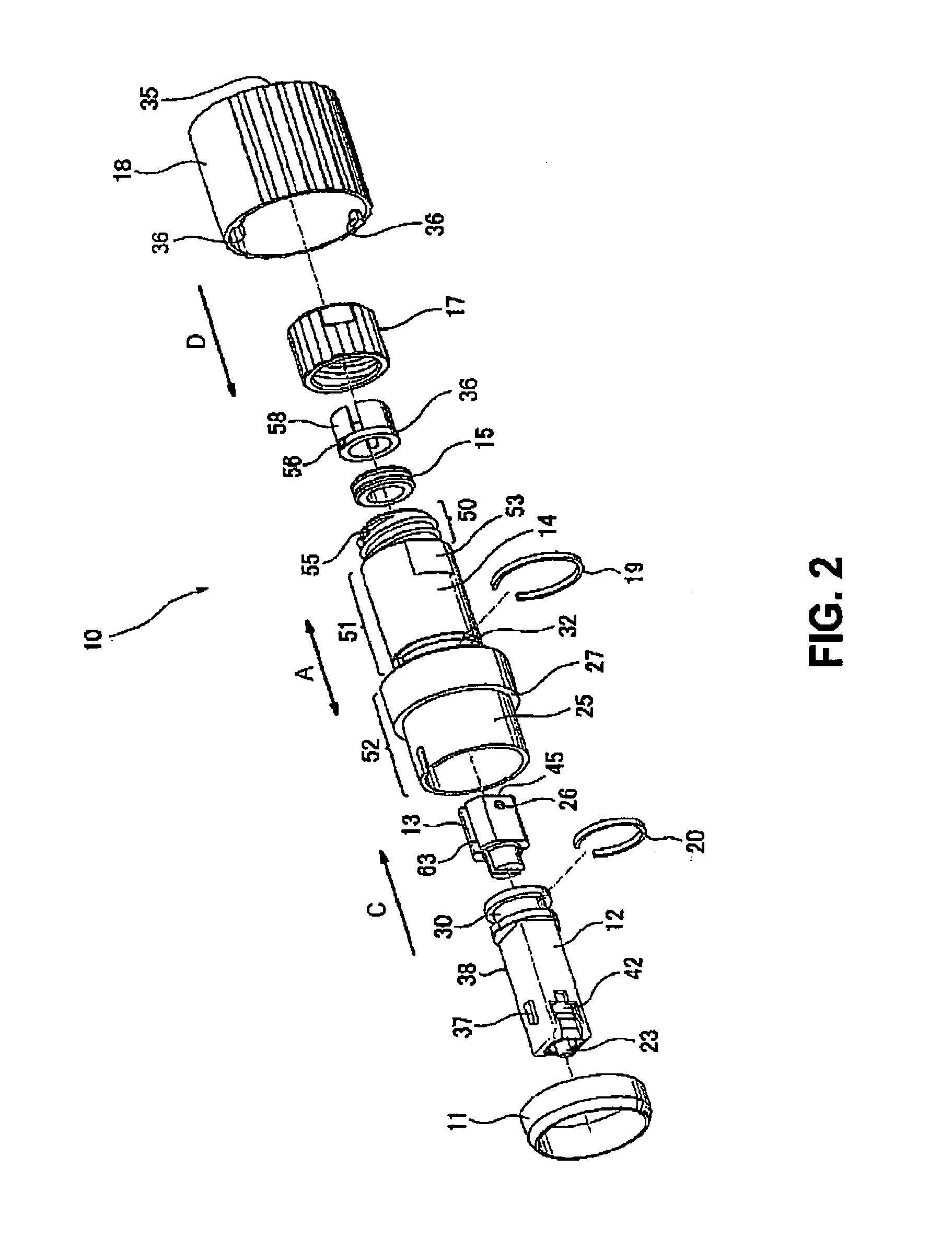
[0033]FIG. 2 is an exploded perspective view showing the waterproof connector 10; FIG. 3 is a plan view showing the waterproof connector 10 and the mating connector 80; FIG. 4 is a sectional view showing the waterproof connector 10 and the mating connector 80 taken along a line 4-4 in FIG. 3; FIG. 5 is a side view showing the waterproof connector 10 and a mating connector 80; and FIG. 6 is a sectional view showing the waterproof connector and the mating connector taken along a line 6-6 in FIG. 5, respectively. While FIG. 1 shows a state when the waterproof connector 10 is not ye...


PUM


Abstract

A waterproof connector is to be connected to a mating connector, and a waterproof apparatus includes the waterproof connector and the mating connector. The waterproof connector includes a connector member to be connected to an adapter member; a connecting member to be connected to a cylindrical portion of a mating connector; and a main body portion. The connector member is able to slide along a facing direction of the connectors in a given range. The waterproof connector and the waterproof apparatus improve an efficiency of the performance by associating the operations with each other.

Description

CROSS-REFERENCES TO RELATED APPLICATIONS[0001]The disclosure of Japanese Patent Application No. 2008-146659, filed on Jun. 4, 2008 is incorporated in the application by reference.BACKGROUND OF THE INVENTION AND RELATED ART STATEMENT[0002]The present invention relates to a waterproof connector and a waterproof apparatus using the waterproof connector.[0003]A conventional waterproof apparatus (waterproof connector) disclosed in Patent Reference is shown in FIG. 10. The conventional waterproof apparatus comprises a pair of a waterproof connector and a mating connector. The waterproof connector includes a connector member 111 fixed to a cable 114; a sealing member 190 capable of being attached to the cable 114 sideway; and a hood member 150 extending along the cable 114 in a state that the cable 114 is inserted therein. The mating connector includes an adapter member 112 and a housing 120 surrounding circularly an outer portion of the adapter member 112.[0004]Patent Reference: Japanese ...

Claims


Application Information

Patent Timeline
Patent Type & Authority Patents(United States)
IPC IPC(8): G02B6/38
CPCH01R13/625H01R13/502G02B6/3816G02B6/3825G02B6/3831G02B6/3891G02B6/3893
Inventor MASUZAKI, YASUHIRO
Owner HIROSE ELECTRIC GROUP
Why Eureka
Try Eureka