
Image pickup apparatus with function of rate conversion processing and control method therefor

a pickup apparatus and rate conversion technology, applied in the field of image pickup apparatuses, can solve the problems of prolonged delay time from image data readout to image display, unnatural reproduction of moving images, and sudden frame dropping, and achieve the effect of reducing unnaturalness

Inactive Publication Date: 2010-12-28
CANON KK
View PDF54 Cites 4 Cited by
  • Summary
  • Abstract
  • Description
  • Claims
  • Application Information

AI Technical Summary

Benefits of technology

[0011]The present invention has another object to provide an image pickup apparatus capable of reducing unnaturalness caused by rate conversion during image display, without performing complex arithmetic processing, and a control method therefor.

Problems solved by technology

According to such a conventional method, however, sudden frame dropping occurs.
Therefore, there is a problem that the reproduction of a moving image seems to be unnatural.
Furthermore, since arithmetic processing for selecting the frame to be thinned out is required, this method is disadvantageous in that delay time from the readout of image data to image display is prolonged.
If the delay time is prolonged in this manner, the method is not suitable for displaying images on a view finder during photographing.

Method used


Image

  • Image pickup apparatus with function of rate conversion processing and control method therefor
  • Image pickup apparatus with function of rate conversion processing and control method therefor
  • Image pickup apparatus with function of rate conversion processing and control method therefor

Examples


first embodiment

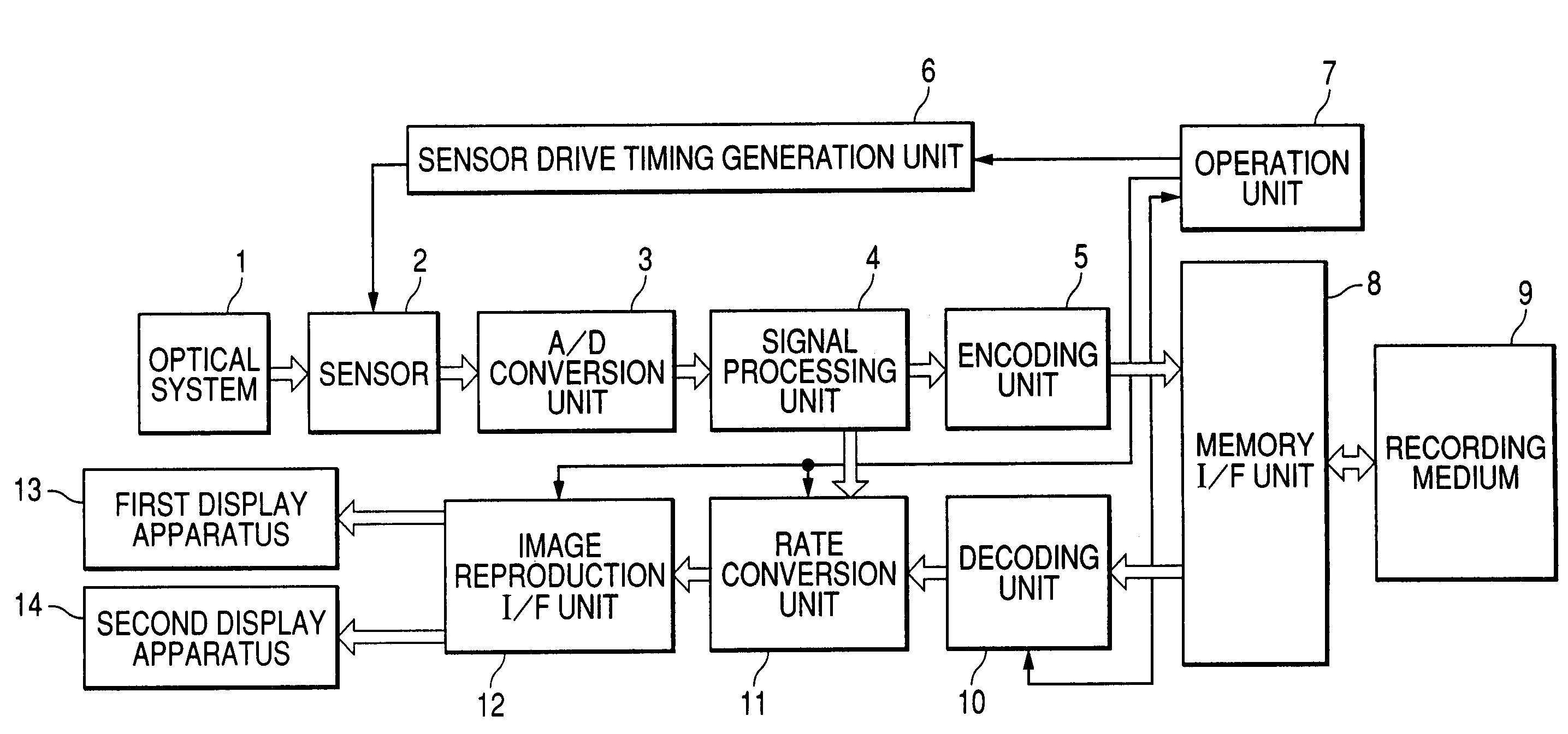
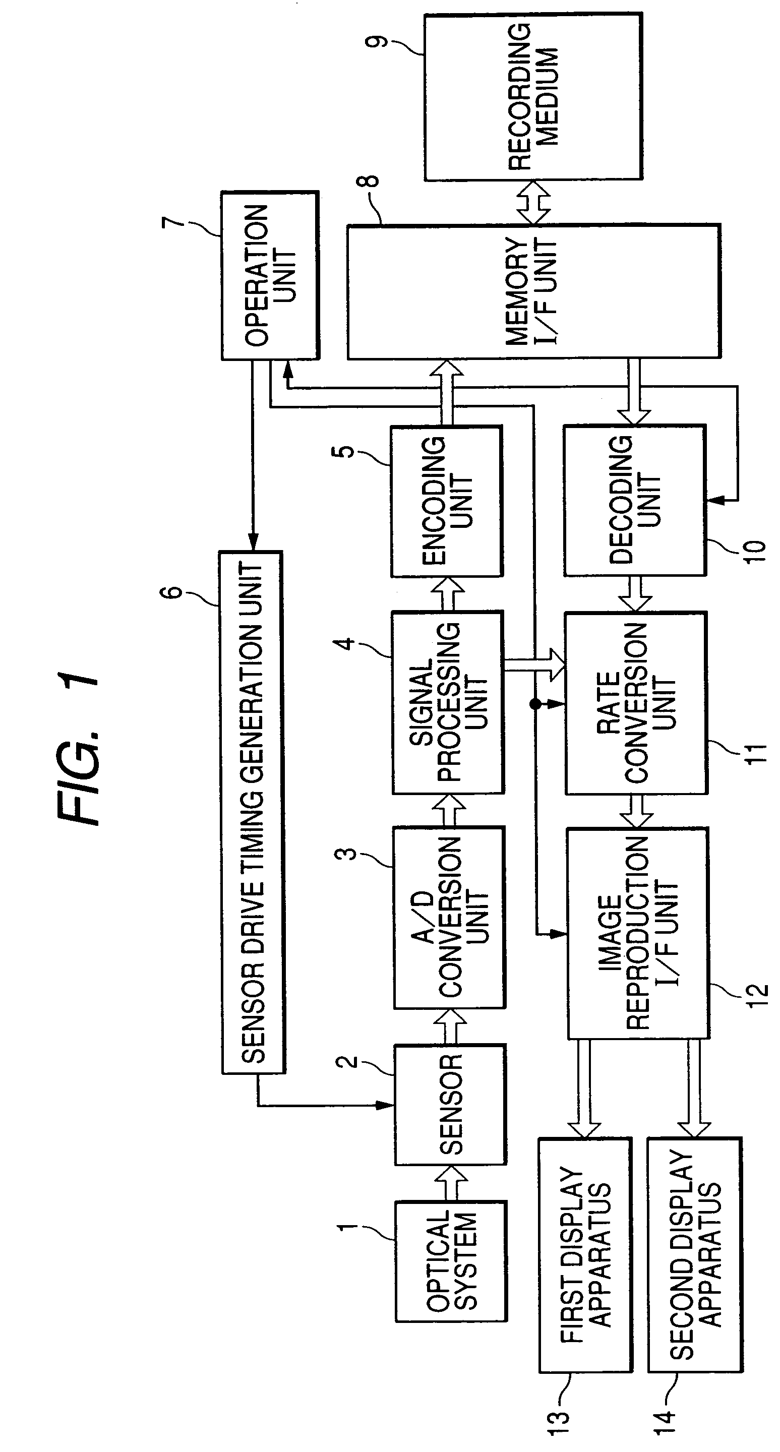
[0036]First, a first embodiment of the present invention will be described. FIG. 1 is a block diagram showing a configuration of an image pickup apparatus according to the first embodiment of the present invention.

[0037]The image pickup apparatus according to this embodiment includes: an optical system 1; a sensor 2; an A / D conversion unit 3; a signal processing unit 4; an encoding unit 5; a sensor drive-timing generation unit 6; an operation unit 7; a memory I / F unit 8; a recording medium 9; a decoding unit 10; a rate conversion unit 11; and an image reproduction I / F unit 12. A first display apparatus 13 and a second display apparatus 14 are connected to the image pickup apparatus.

[0038]The optical system 1 includes of, for example, an optical lens for imaging object light. The sensor 2 converts the object light imaged by the optical system 1 into an analog image signal to output it. The A / D conversion unit 3 converts the analog image signal output from the sensor 2 into a digital ...

second embodiment

[0100]Next, a second embodiment of the present invention will be described. In this embodiment, an operation of the rate conversion unit 11 in the case of reproduction at a variable speed, that is, not normal-speed reproduction, for example, slow reproduction is selected in the operation unit 7, will be described.

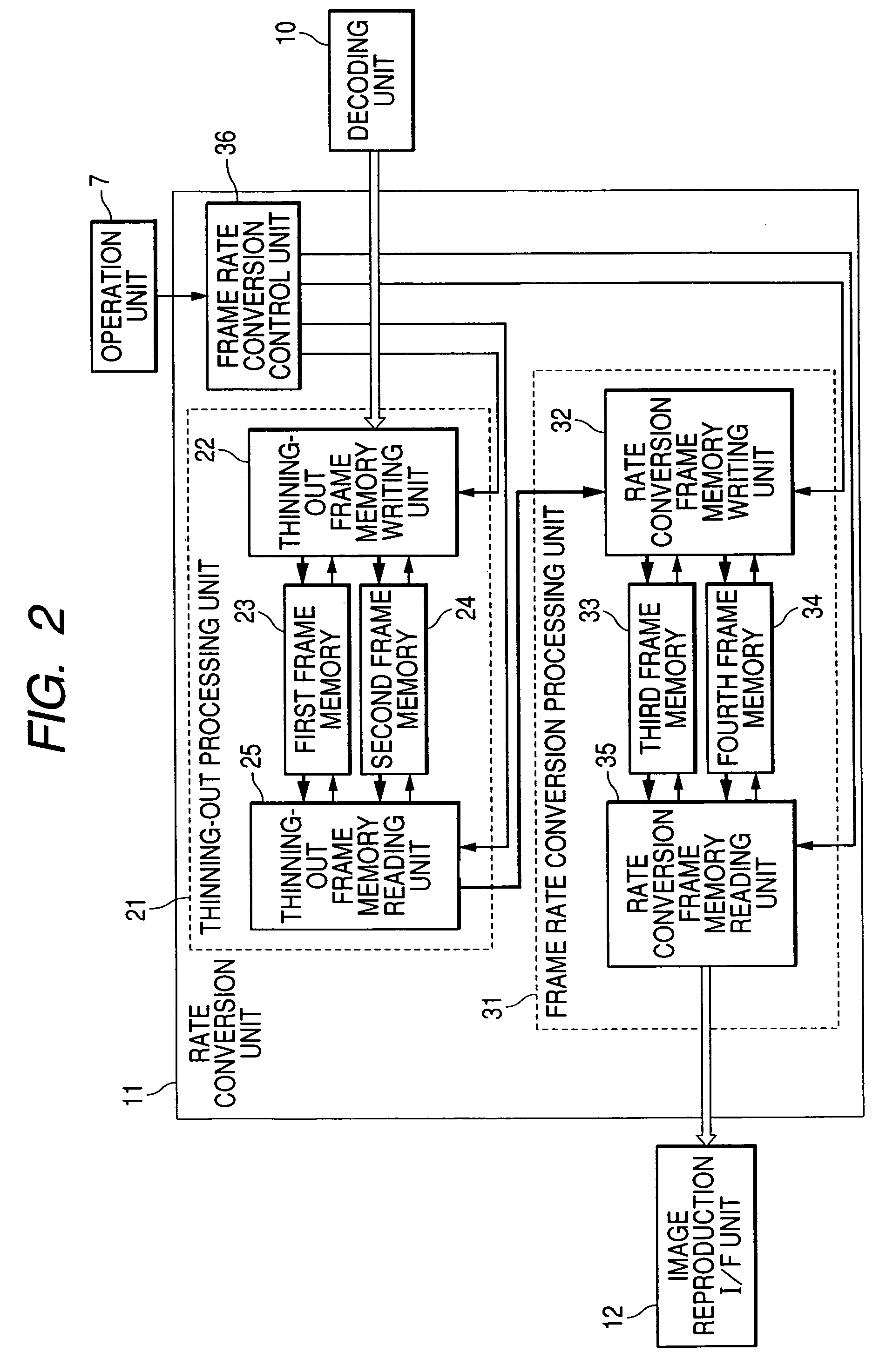
[0101]Since a reproduction speed is set in the operation unit 7 in the second embodiment, the frame rate conversion control unit 36 generates a control signal in consideration of not only the recording rate and the display rate but also the reproduction speed. Hereinafter, the operation of the frame rate conversion control unit 36 will be described. FIG. 10 is a flowchart showing the operation of the frame rate conversion control unit 36 in reproduction at a variable speed.

[0102]During a variable-speed operation, the frame rate conversion control unit 36 compares a value obtained by multiplying the recording rate set in the operation unit 7 by a reproduction speed magnifica...


PUM


Abstract

A rate conversion unit determines a frame thinning-out rate to thin out frames on the basis of a recording rate at the time of photographing and a display rate for display on a display apparatus so that a temporal updating interval of a video image between continuous fields becomes constant. After that, a frame is repeatedly inserted so that a frame rate becomes equal to the display rate.

Description

BACKGROUND OF THE INVENTION[0001]1. Field of the Invention[0002]The present invention relates to an image pickup apparatus having a function of rate conversion processing to deal with the case where a frame rate of recording and a frame rate of reproduction differ from each other, and a control method therefor.[0003]2. Related Background Art[0004]When image data is recorded by an image pickup apparatus capable of switching between NTSC and PAL to reproduce of image data, a frame rate of image data to be recorded differs from a display type of a display apparatus in some cases.[0005]In order to solve this problem, a technique of converting a frame rate is disclosed in Japanese Patent Application Laid-open No. 2004-80327 and Japanese Patent Application Laid-open No. 2004-48530.[0006]For example, Japanese Patent Application Laid-open No. 2004-80327 discloses a method of performing frame rate conversion processing using thinning-out to output image data in conformity with a display rate...

Claims


Application Information

Patent Timeline
Patent Type & Authority Patents(United States)
IPC IPC(8): G06K9/36H04N7/01
CPCH04N5/232H04N5/772H04N23/633
Inventor WATANABE, YOSHINORIRENGAKUJI, HIDEYUKI
Owner CANON KK
Learn More