Radiolucent chest assembly

a radiolucent and chest assembly technology, applied in the field of wireless monitoring systems, can solve the problems of not being a direct replacement for stationary ecg monitors, not being developed or suitable for portable use, and requiring a significant amount of set up time, so as to improve comfort and mobility for patients, reduce setup times, and be convenient for health practitioners to use

Inactive Publication Date: 2010-12-28
LIFESYNC
View PDF159 Cites 41 Cited by
  • Summary
  • Abstract
  • Description
  • Claims
  • Application Information

AI Technical Summary

Benefits of technology

[0013]The ECG system eliminates the wires that ordinarily tether an ECG patent to an ECG monitor by replacing conventional wires with a radio link. The present invention is lightweight and portable—thereby providing increased comfort and mobility to the patient. In addition, the present invention requires decreased setup times and is more convenient for health practitioners to use than conventional ECG systems. In addition, to collecting and transmitting ECG signals, the present invention is capable of collecting and transmitting other physiological data. For example, the body electronics unit is capable of transmitting and the base station is capable of receiving and processing physiological data pertaining to a patient's pulse, respiration rate, heart rate, temperature, blood pressure, EEG signals, and pulse oximeter signals, or the like.

Problems solved by technology

These systems, however, are generally stationary and are not developed or suitable for portable use.
While portable telemetry systems exist, they are not a direct replacement for stationary ECG monitors.
Moreover, because conventional systems use multiple cables or wires, and are cumbersome and uncomfortable for the patient, and require a significant amount of set up time.
Furthermore, in both traditional wired systems and wireless systems, portions of the conventional electrodes or sensors that connect to the cables, wires, or chest assemblies are not standardized.
Accordingly, many of the conventional electrodes or sensors are not compatible for use with many of the wires, leads, or chest assemblies used in physiological data collections systems.
Those spring loaded, female snap pieces, however, are substantially more expensive than other conventional female snap pieces.
Nevertheless, because the increased cost of the spring loaded, female snap pieces can be amortized over the life of the cable or lead set, the increased costs of those snap pieces are not a major consideration for conventional wired systems.
However, the increased costs of those female snap pieces cannot be amortized over the life of a chest assembly used in a typical wireless or telemetry system since the chest assemblies used in such systems are generally discarded after each patient use.
Accordingly, the increased cost of those spring loaded, female snap pieces make them unsuitable for use with a chest assemblies used in a wireless or telemetry system.
A major disadvantage to such chest assemblies, however, is that those chest assemblies must be hermetically packaged to preserve the integrity of the aqueous silver chloride gel on the electrodes integrally connected to those chest assemblies.
As a result, the cost of such chest assemblies is significant.
Because those chest assemblies are designed to be disposed of after each patient use, the increased cost of those chest assemblies make them cost inefficient.
Non-disposable radiolucent electrode leads exist but cost in excess of a thousand dollars per radiolucent lead set.

Method used


Image

  • Radiolucent chest assembly
  • Radiolucent chest assembly
  • Radiolucent chest assembly

Examples


Embodiment Construction

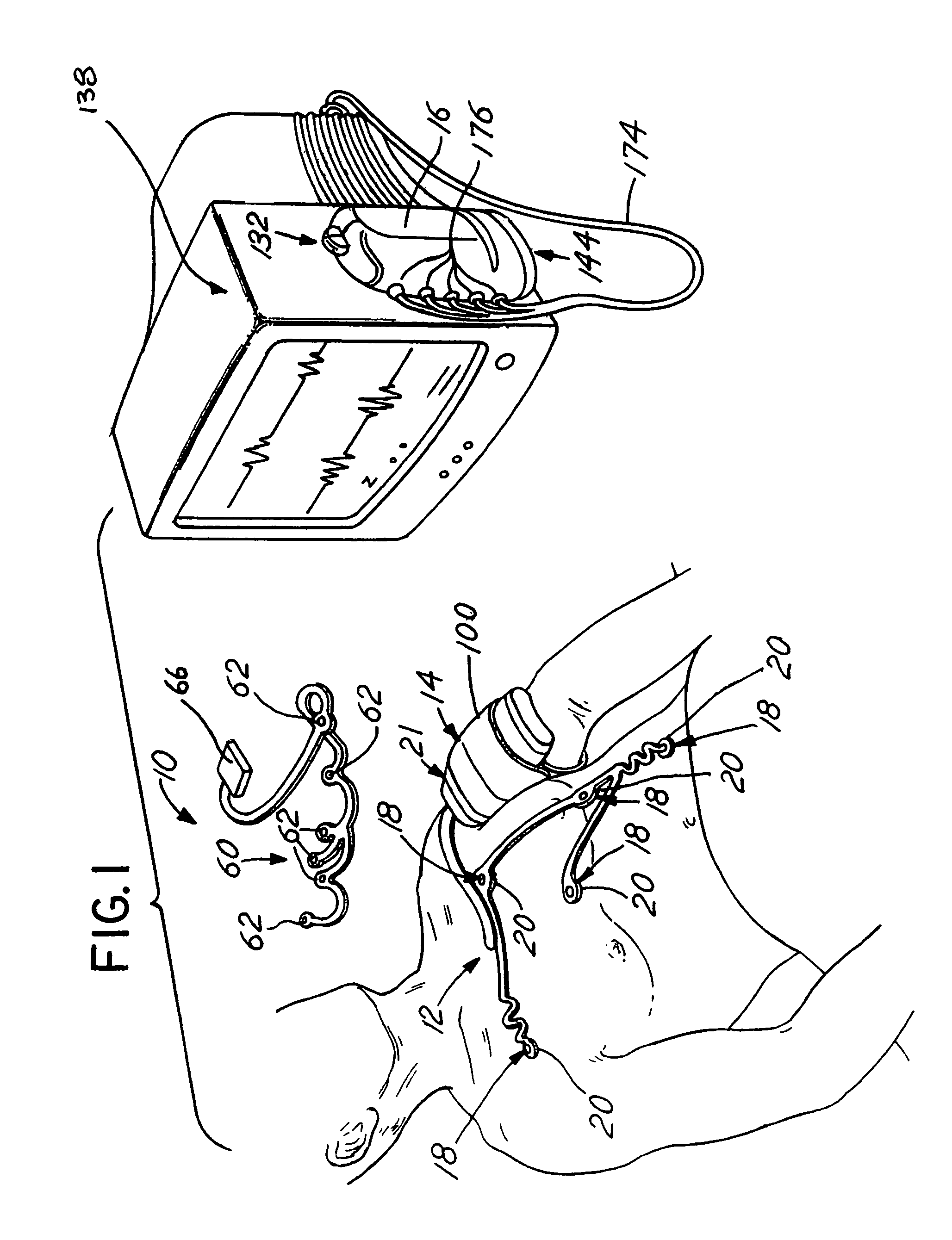
[0059]For a better understanding of the present invention, reference may be had to the following detailed description taken in conjunction with the appended claims and accompanying drawings. Briefly, the present invention relates to a wireless, portable ECG system. Referring to FIG. 1, the ECG system 10 comprises a chest assembly 12, a body electronics unit 14, and a base station 16.

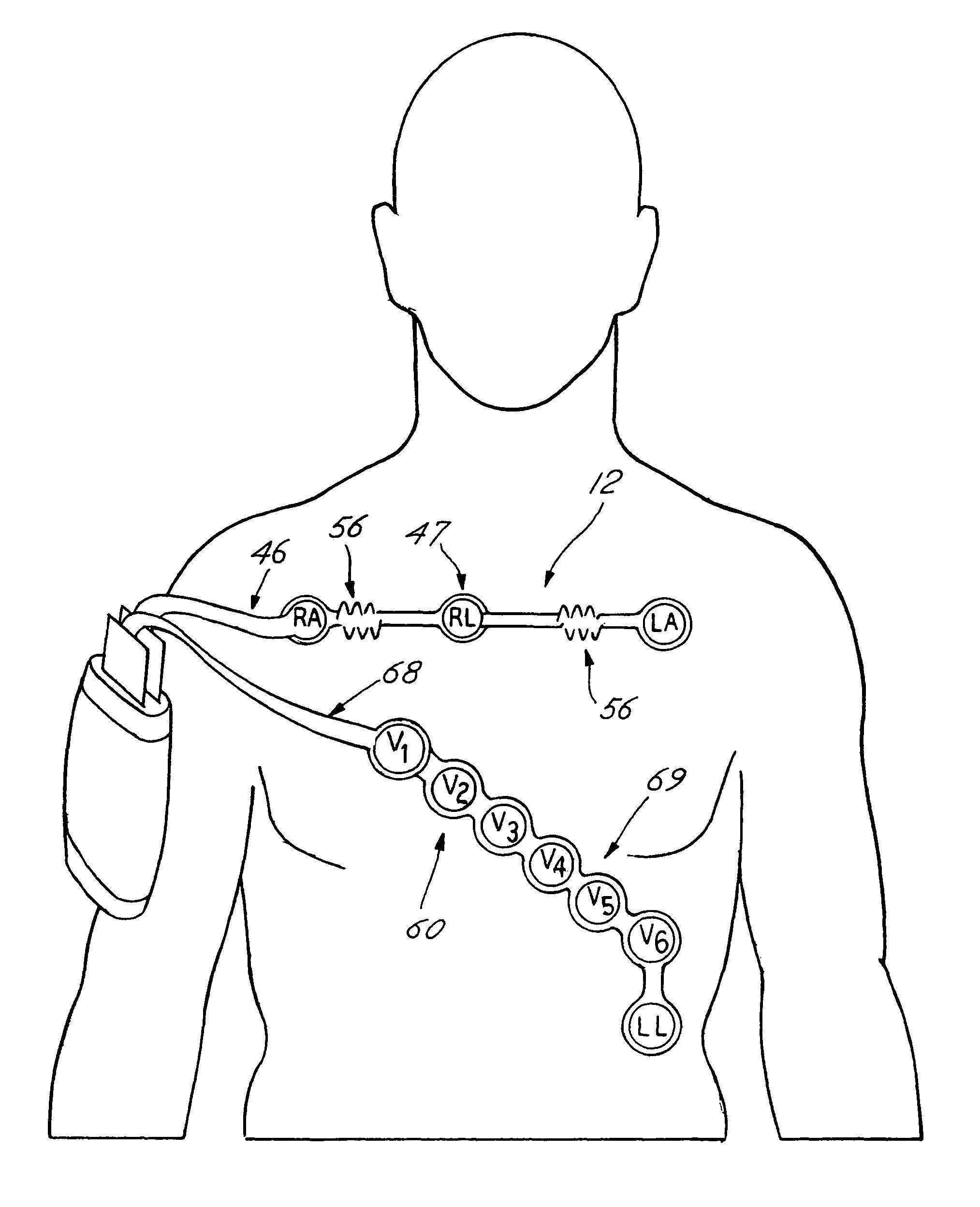
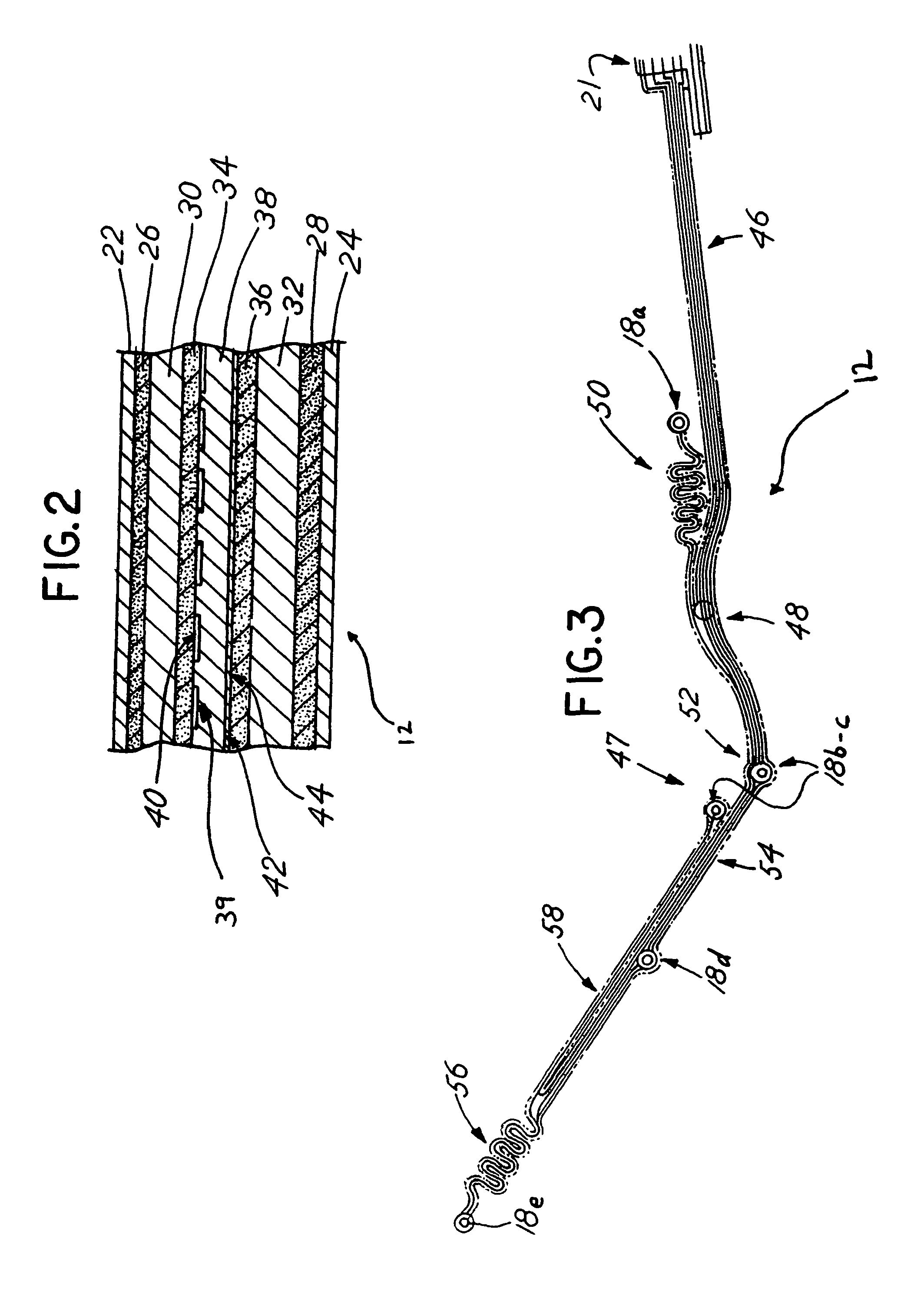
[0060]The chest assembly 12 is a one-piece flexible circuit that connects a plurality of electrode connectors 18. The electrode connectors 18 are configured to connect to electrodes 20 or electrically conductive adhesives. Preferably, the electrode connectors 18 have snap terminals that connect to electrodes 20 having snap terminals. Each electrode connector 18 connects to an electrically conductive element or trace for transmitting electrical signals. The electrically conductive elements or traces run along the chest assembly 12 and connect to a chest assembly connector 21. Alternatively, the chest asse...


PUM


Abstract

A wireless monitoring system and, more particularly, a wireless monitoring system for detecting and transmitting physiological data. The present invention detects physiological data relating to a patients cardiac activity and respiration rate and transmits the data to a remote base station via telemetry. The base station processes the data so that the data can be displayed by an ECG monitor.

Description

RELATED APPLICATIONS[0001]The application is a continuation and claims the benefit of the filing date pursuant to 35 U.S.C. §120 of application Ser. No. 10 / 439,356 filed on May 16, 2003 which in turn is a continuation-in-part of and claims the benefit of the filing date pursuant to 35 U.S.C. §120 of application Ser. No. 09 / 998,733, for a WIRELESS ECG SYSTEM, filed Nov. 30, 2001, which in turn, is a continuation-in-part of and claims the benefit of the filing date pursuant to 35 U.S.C. §120 of application Ser. No. 09 / 908,509, for a WIRELESS ELECTROCARDIOGRAPH SYSTEM AND METHOD, filed Jul. 17, 2001, the disclosure and content of which is hereby incorporated by reference in its entirety. This application also claims the benefit of the filing date pursuant to 35 U.S.C. §120 of Application Ser. No. 60 / 392,882, for a FASTENER ASSEMBLY, filed Jul. 1, 2002, the disclosure and content of which is hereby incorporated by reference in its entirety.FIELD OF THE INVENTION[0002]The present inventi...

Claims


Application Information

Patent Timeline
Patent Type & Authority Patents(United States)
IPC IPC(8): A61B5/04A61B5/00A61B5/274A61N1/08
CPCA61B5/0006A61B5/04085A61B5/04087A61B5/6841A61B5/0416A61B5/0424A61B2562/08A61B5/7232A61B2562/17A61B5/259A61B5/274A61B5/282A61B5/276
Inventor ISTVAN, RUDGREGORY, BILLSOLOVAY, KENNETHCHASTAIN, DAVID PAULGUNDLACH, JOHN DAVIDHOPMAN, NICHOLAS C.WILLIAMS, DANIEL L.LODATO, FRANCO
Owner LIFESYNC
Why Eureka
Try Eureka