Connector for sturdily connecting flexible circuit boards

Inactive Publication Date: 2011-01-04
TAIWAN SUNCAGEY INDAL
View PDF2 Cites 22 Cited by
  • Summary
  • Abstract
  • Description
  • Claims
  • Application Information

AI Technical Summary

Benefits of technology

[0012]As the fixed arm is formed with the snap part close to the pushing part, and two sides of the flexible circuit board are formed respectively with the latching part, when the pressing element displaces toward a pre-determined direction by being acted upon by a displacement operation, the abutting part of the pressing element can push the pushed part of the movable arm, allowing the movable arm to make an angular displacement, which further enables the flexible circuit board to displace downward, such that the snap part of the fixed arm c

Problems solved by technology

Nevertheless, the aforementioned connector has already been a very well-known technology and there is a vendor who develops a co

Method used


Image

  • Connector for sturdily connecting flexible circuit boards
  • Connector for sturdily connecting flexible circuit boards
  • Connector for sturdily connecting flexible circuit boards

Examples


Example

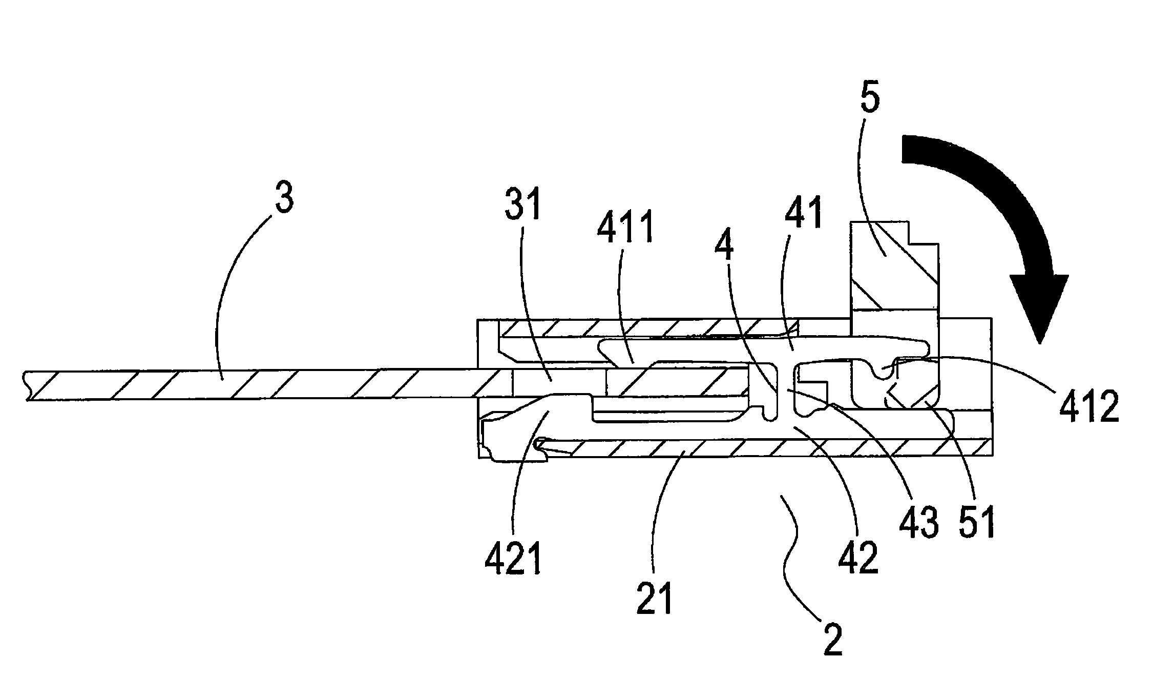
[0023]Referring to FIG. 3 and FIG. 4, it shows a three-dimensional schematic view and a cutaway view, of a preferred embodiment of the present invention. As shown in the drawings, a connector 2 of the present invention comprises:

[0024]a housing 21;

[0025]a flexible circuit board 3, which provides for electric connection with the connector 2 and two sides of which are formed respectively with a latching part 31;

[0026]a terminal 4, which is provided with a movable arm 41 and a fixed arm 42, with both arms being extended toward a same direction and parallel provided, wherein an end of the movable arm 41 is provided with a pushing part 411, the other end is provided with a pushed part 412, the fixed arm 42 is fixed by using the housing 21 and is formed with a snap part 421 close to the pushing part 411, and the movable arm 41 and the fixed arm 42 are formed as one unit by using a connection part 43; and

[0027]a pressing element 5, which is provided with an abutting part 51 able to push th...


PUM


Abstract

A connector includes a housing, a flexible circuit board, a terminal and a pressing element. The flexible circuit board, two sides of which are formed respectively with a latching part, is electrically connected with the connector. The terminal includes a movable arm and a fixed arm which are extended toward a same direction and parallel provided. An end of the movable arm is a pushing part, and the other end is a pushed part. The fixed arm is fixed by using the housing and includes a snap part close to the pushing part. The pressing element has an abutting part to push the pushed part. Accordingly, when the pressing element is acted upon by a displacement operation to displace toward a pre-determined direction, the snap part of the fixed arm is engaged into the latching part of the flexible circuit board which is therefore effectively fixed at the connector.

Description

BACKGROUND OF THE INVENTION[0001]a) Field of the Invention[0002]The present invention relates to a connector which is used for electrically connecting a flexible circuit board, and more particularly to a connector which is able to fix a flexible circuit board effectively.[0003]b) Description of the Prior Art[0004]To enable a flexible circuit board achieving an electric connection effect, this kind of flexible circuit board will usually be connected to a connector which includes a housing, a terminal and a pressing element. When the pressing element of the connector is operated, the pressing element can operate the terminal, allowing the terminal to be pressed onto the flexible circuit board.[0005]Nevertheless, the aforementioned connector has already been a very well-known technology and there is a vendor who develops a connector which can prevent a user from pulling the flexible circuit board, resulting in that the flexible circuit board falls off. Referring to FIG. 1 and FIG. 2, i...

Claims


Application Information

Patent Timeline
CPCH01R12/79H01R12/88
Inventor CHEN, YEN-LIN
Owner TAIWAN SUNCAGEY INDAL
Why Eureka
Try Eureka