Method of forming fine pattern

Inactive Publication Date: 2009-02-12
RIKEN
View PDF9 Cites 9 Cited by
  • Summary
  • Abstract
  • Description
  • Claims
  • Application Information

AI Technical Summary

Benefits of technology

[0035]Since the invention is constituted as described above, it results in such excellent advantageous effects that it becomes possible to transfer a fine pattern formed on a mold to a patterning material at a low temperature and low pressure for a short period of time in case of the imprinting process wherein the mold is pressed against the patterning material to transfer the fine patter of the mold to the patterning material; and that after the fine pattern of the mold is transferred

Problems solved by technology

However, it has been pointed out that a conventional patterning material made from an organic material such as PMMA involves such problems that the patterning material absorbs easily moisture, that it exhibits a weak resistance to chemicals, that it has a poor thermal resistance, i.e., when a temperature is raised, the fine pattern transferred deforms easily, and that it has a comparatively low hardness; consequently, the use conditions thereof are inevitably restricted.
However, an inorganic material has a high melting point so that it is hard at normal temperatures, consequently there is such problem that a further requirement is added as to pattern formation wherein a mold is pressed against a patterning material to transfer a fine pattern of the mold to the patterning material, and this process must be conducted at a high temperature and high pressure, besides the processi

Method used


Image

  • Method of forming fine pattern
  • Method of forming fine pattern
  • Method of forming fine pattern

Examples


first embodiment

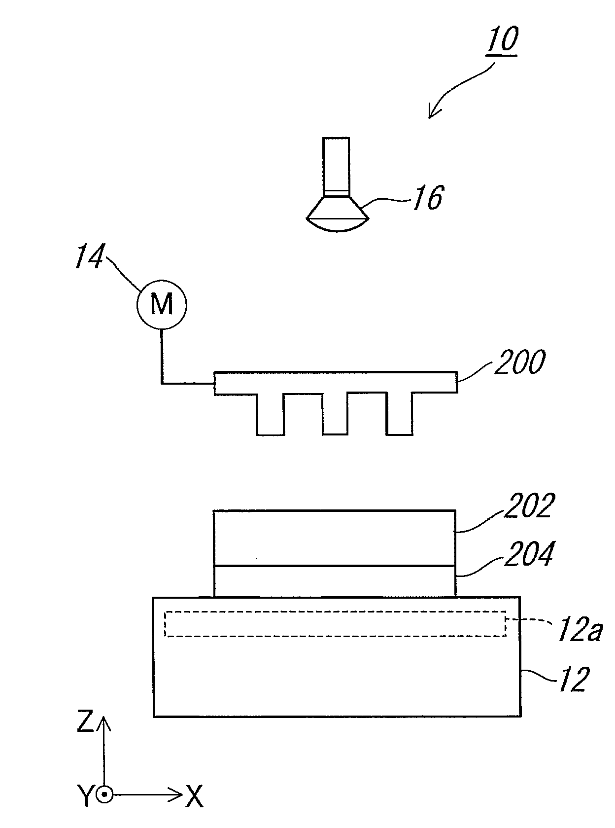
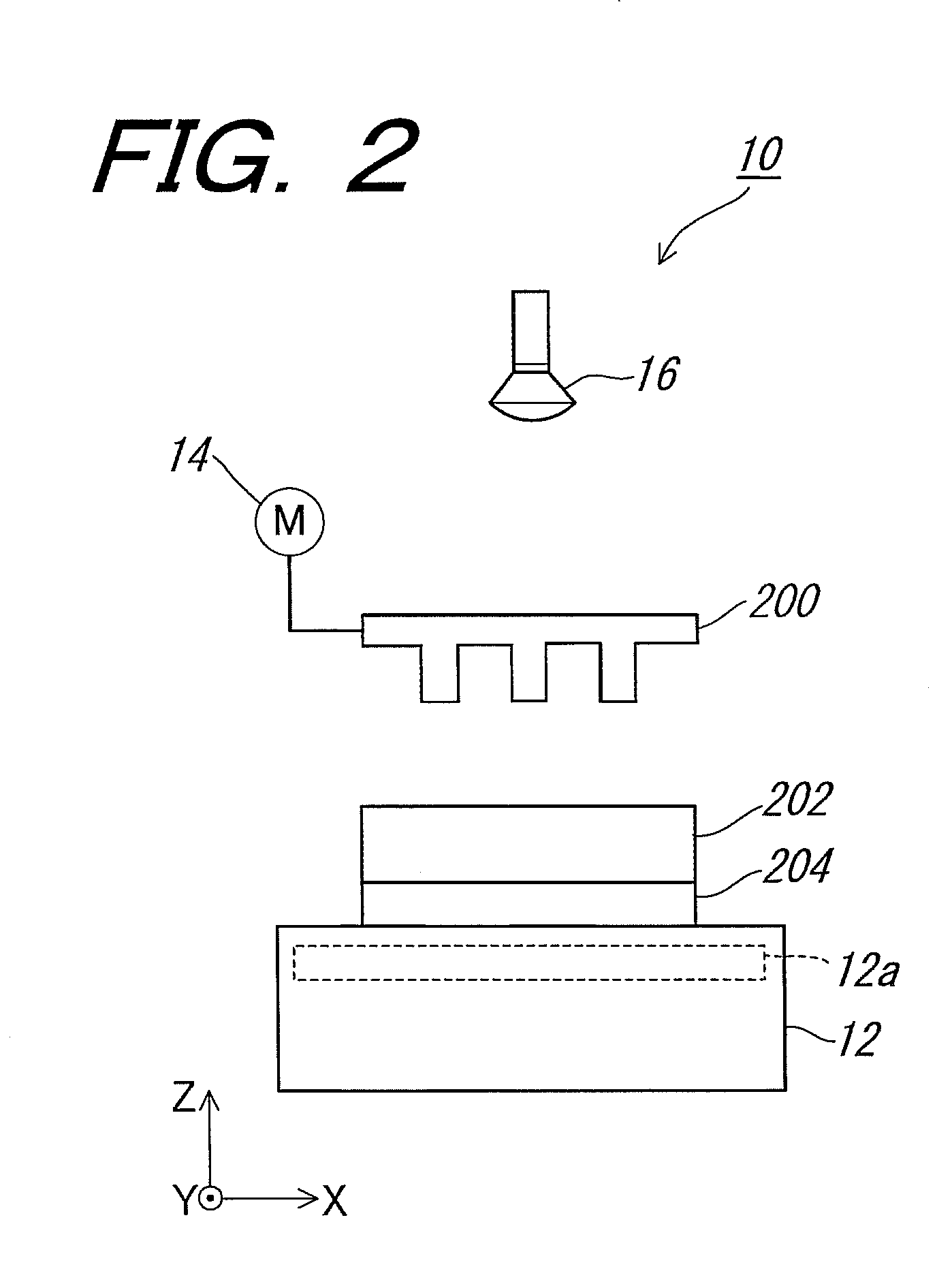
[0070]First, the first embodiment of the method of forming a fine pattern according to the invention will be described. In the case that the first embodiment of the method of forming a fine pattern according to the invention is conducted, for example, a nanoimprint apparatus 10 as shown in FIG. 2 is used for pressing a mold against a patterning material.

[0071]First, the nanoimprint apparatus 10 will be described. The nanoimprint apparatus 10 is provided with a sample holder 12 and adapted to be capable of placing a substrate 204 on the surface of the sample holder 12 wherein a patterning material 202 made from polysilane has been formed on the upper surface of substrate 204. A heater 12a is housed in the sample holder 12.

[0072]On one hand, a mold 200 on the under surface of which a fine structure with recesses / protrusions is formed is provided with a stepping motor 14 by which the mold 200 is driven movably along Y-Z directions.

[0073]Moreover, a superhigh pressure mercury lamp 16 fo...

second embodiment

[0123]Next, the second embodiment of the method of fine-pattern formation of the invention will be described wherein the detailed description of the same or equal constitutions, functions, and treatment contents with or to those of the first embodiment of the method of fine-pattern formation of the invention as described above will be optionally omitted by indicating or applying the same terms or reference characters as that of the first embodiment.

[0124]The method of fine-pattern formation according to the second embodiment of the invention differs from that of the first embodiment in the following points.

[0125]Namely, it is arranged in the first embodiment in such that the mold 200 is irradiated with ultraviolet from the side of the mold 200 to transmit the mold 200, and then the patterning material 202 is irradiated with the ultraviolet during the series of treatment steps, or that the substrate 204 on which the patterning material 202 is to be formed is made from a material such...


PUM

PropertyMeasurementUnit
Temperatureaaaaaaaaaa
Pressureaaaaaaaaaa

Abstract

A method of fine-pattern formation in which in forming a pattern, a fine pattern formed in a mold can be transferred to a pattering material in a short time at a low temperature and low pressure and, after the transfer of the fine pattern to the patterning material, the fine pattern formed in the patterning material does not readily deform. The method for fine-pattern formation comprises: a first step in which a mold having a fine structure with recesses/protrusions is pressed against a pattering material comprising a polysilane; a second step in which the patterning material is irradiated with ultraviolet to photooxidize the patterning material; a third in which the pressing of the mold against the patterning material is relieved and the mold is drawn from the pattering material; and a fourth step in which that surface of the patterning material to which the fine pattern has been transferred is irradiated with an oxygen plasma to oxidize the surface.

Description

TECHNICAL FIELD[0001]The present invention relates to a method of forming a fine pattern, and more particularly to a method of forming a fine pattern for forming the fine pattern having a fine structure with recesses / protrusions of nm order on a patterning material.BACKGROUND ART[0002]Heretofore, a nanoimprint technology has been known as a method for forming a fine pattern having a fine structure with recesses / protrusions of nm order.[0003]In this connection, a technique of lithography in which a nanoimprint technology is applied has been heretofore used. The technique concerns a method which is conducted as shown in, for example, FIGS. 1(a), 1(b), and 1(c) in such that a mold 100 (the mold may be made from, for example, a Si substrate.) on which a fine pattern having a fine structure with recesses / protrusions of nm order is formed, and a substrate 104 such as a Si substrate on which a patterning material 102 made from a resin material such as PMMA being an organic material to be u...

Claims


Application Information

Patent Timeline
IPC IPC(8): B29C59/16
CPCB81C1/00031B81C1/00111B81C2201/0152B81C2201/0153B82Y10/00H01L21/76817G03F7/0002H01L21/31H01L21/3121H01L21/316B82Y40/00H01L21/02208H01L21/02107
Inventor OKINAKA, MOTOKITSUKAGOSHI, KAZUHITOAOYAGI, YOSHINOBU
Owner RIKEN
Why Eureka
Try Eureka