

Light source device and light projecting device
- Summary
- Abstract
- Description
- Claims
- Application Information
AI Technical Summary
Benefits of technology
Problems solved by technology
Method used
Image

Examples
embodiment
[0057][1. Basic Configuration of Light Source Device]
[0058]A basic configuration of a light source device according to an embodiment will be described with reference to FIG. 1 and FIG. 2A.
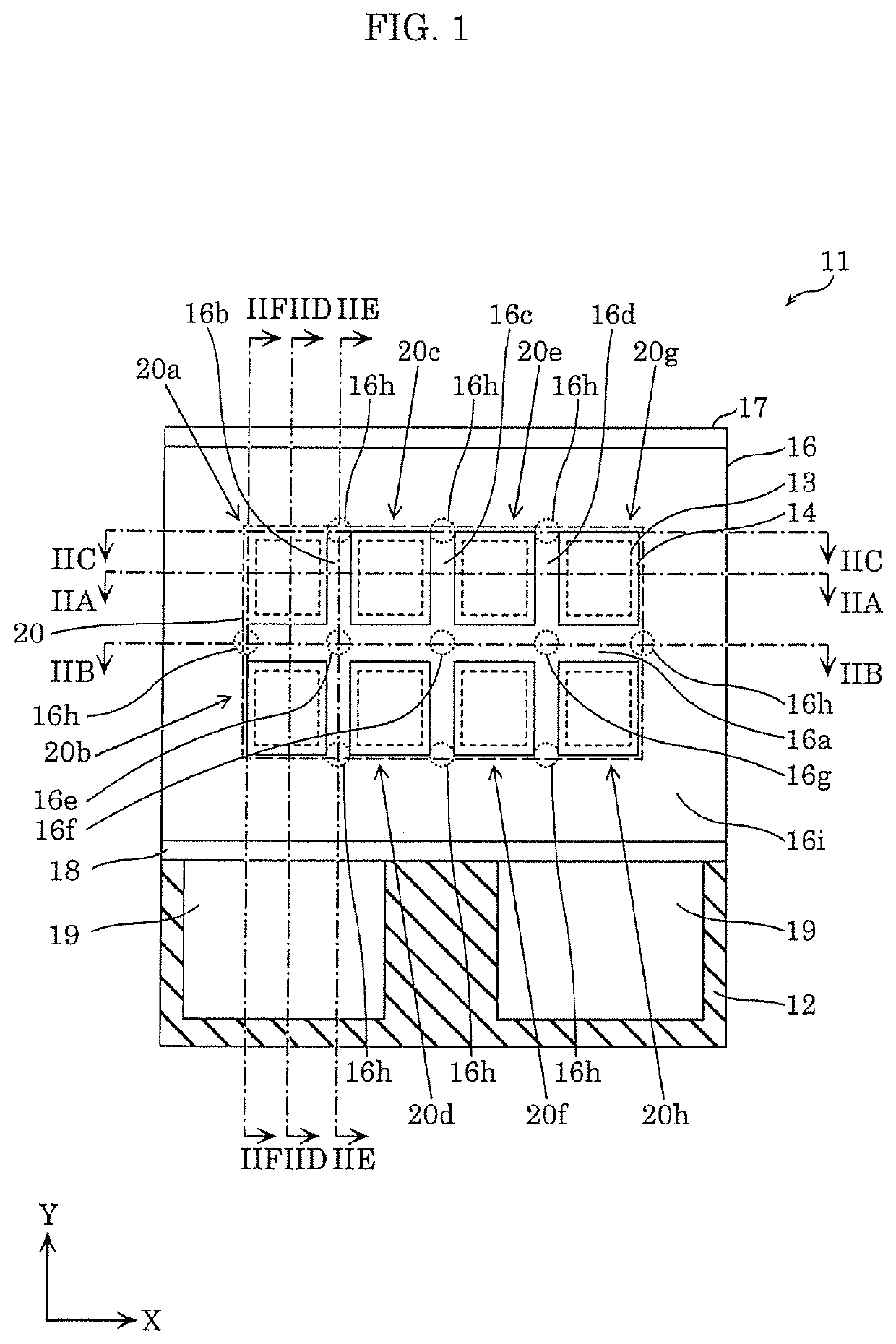
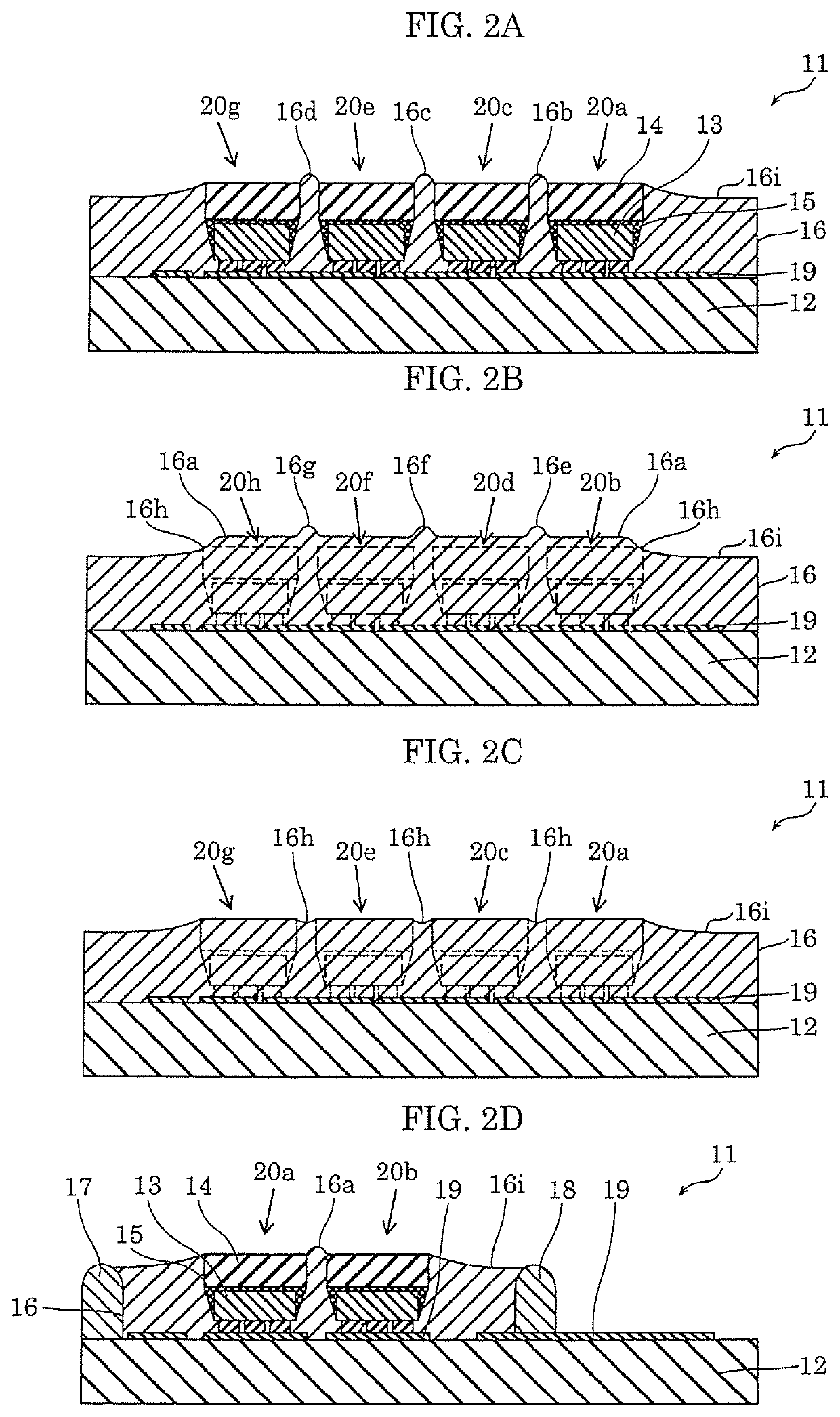
[0059]FIG. 1 is a schematic top view of an example of a configuration of light source device 11 according to the embodiment. FIG. 2A schematically illustrates a cross-section taken along IIA-IIA of light source device 11 in FIG. 1. As illustrated in FIG. 1, light source device 11 includes substrate 12, light-emitting unit matrix 20, and reflective resin 16. In the present embodiment, light source device 11 further includes first dam 17 and second dam 18.
[0060]Substrate 12 is a mounting substrate on which light-emitting unit matrix 20 is mounted. Light-emitting unit matrix 20 is a light emitter which includes a plurality of light-emitting units arranged in a matrix on substrate 12. The plurality of light-emitting units include first light-emitting unit 20a and second light-emitting unit 20b adjacent...
PUM
 Abstract
Description
Claims
Application Information