Vehicle Door Latch System

Active Publication Date: 2018-12-27
WOOBO TECH
View PDF0 Cites 3 Cited by
  • Summary
  • Abstract
  • Description
  • Claims
  • Application Information

AI Technical Summary

Benefits of technology

[0032]As described above, according to a vehicle door latch system of the present invention, there are advantageous effects as follows.
[0033]By comprising: a locking member spring applying an elastic force to the locking member in the opposite direction of an external force when the locking member is moved by the external force; a locking guide member rotatably installed in a housing; and a cam-part formed in a locking member for guiding the locking guide member and formed with a stopping slot; so that the structure of the device becomes simple, and at the same time, releasing of the locking member is prevented when the latch is rotated by the main gear even when the locking member is moved by the same main gear used for the latch.
[0034]The stopping slot is formed by a first inclined surface and a second inclined surface facing each other, and the first inclined surface is formed to be longer than the second inclined surface so that the movement of the locking member can be performed smoothly.
[0035]The cam-part can be easily formed e

Problems solved by technology

However, such vehicle door latch system of the prior art has a problem wherein an unnecessary force is applied to the various components such as a latch connected to the door lever and the like when the door lever is pulled while the door is being locked

Method used


Image

  • Vehicle Door Latch System
  • Vehicle Door Latch System
  • Vehicle Door Latch System

Examples


embodiment 1

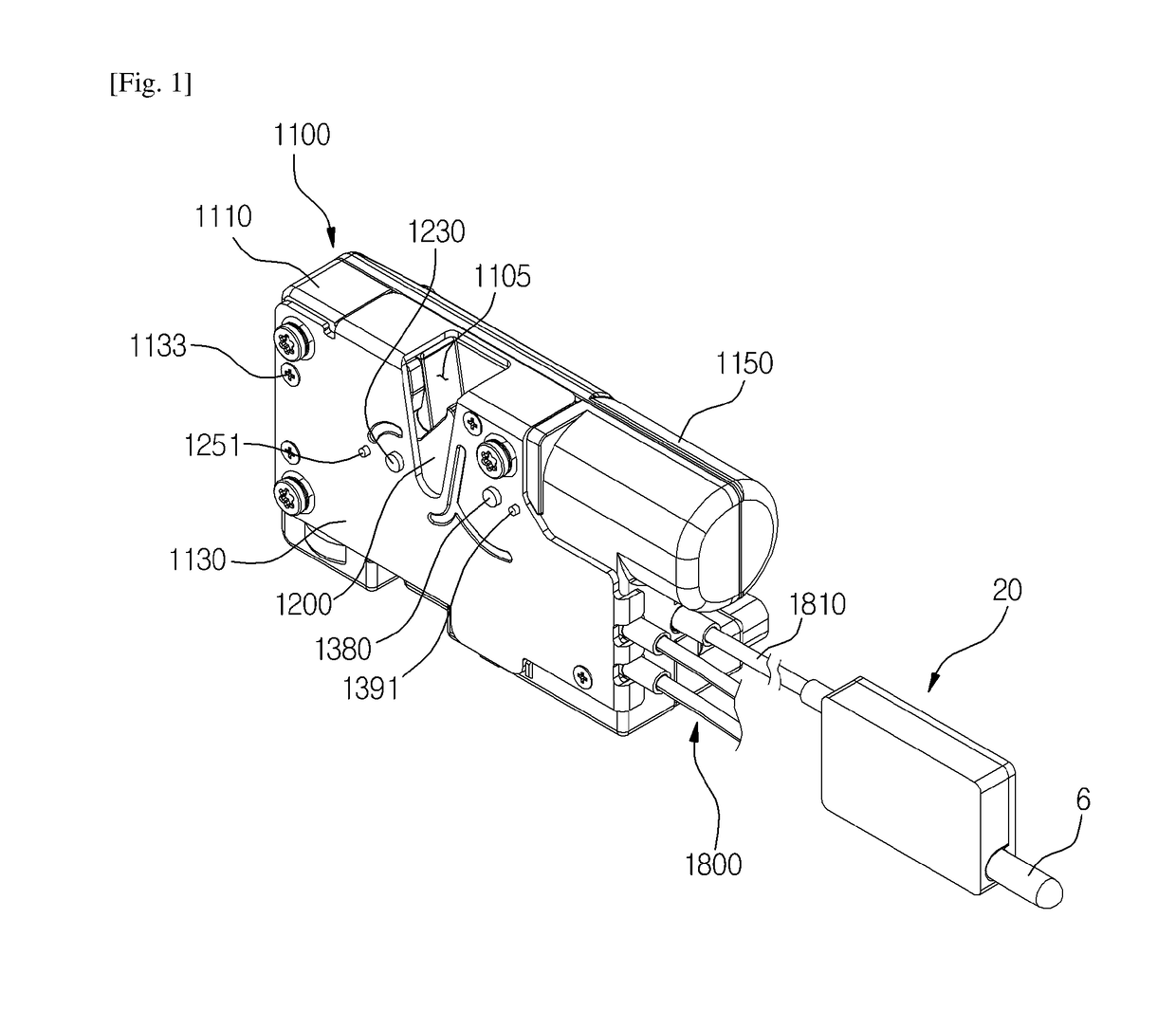
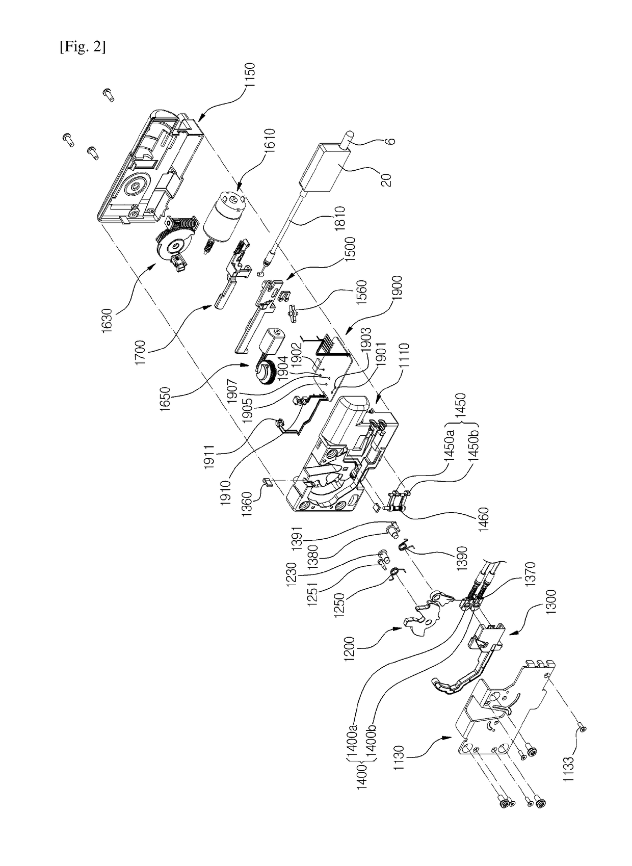
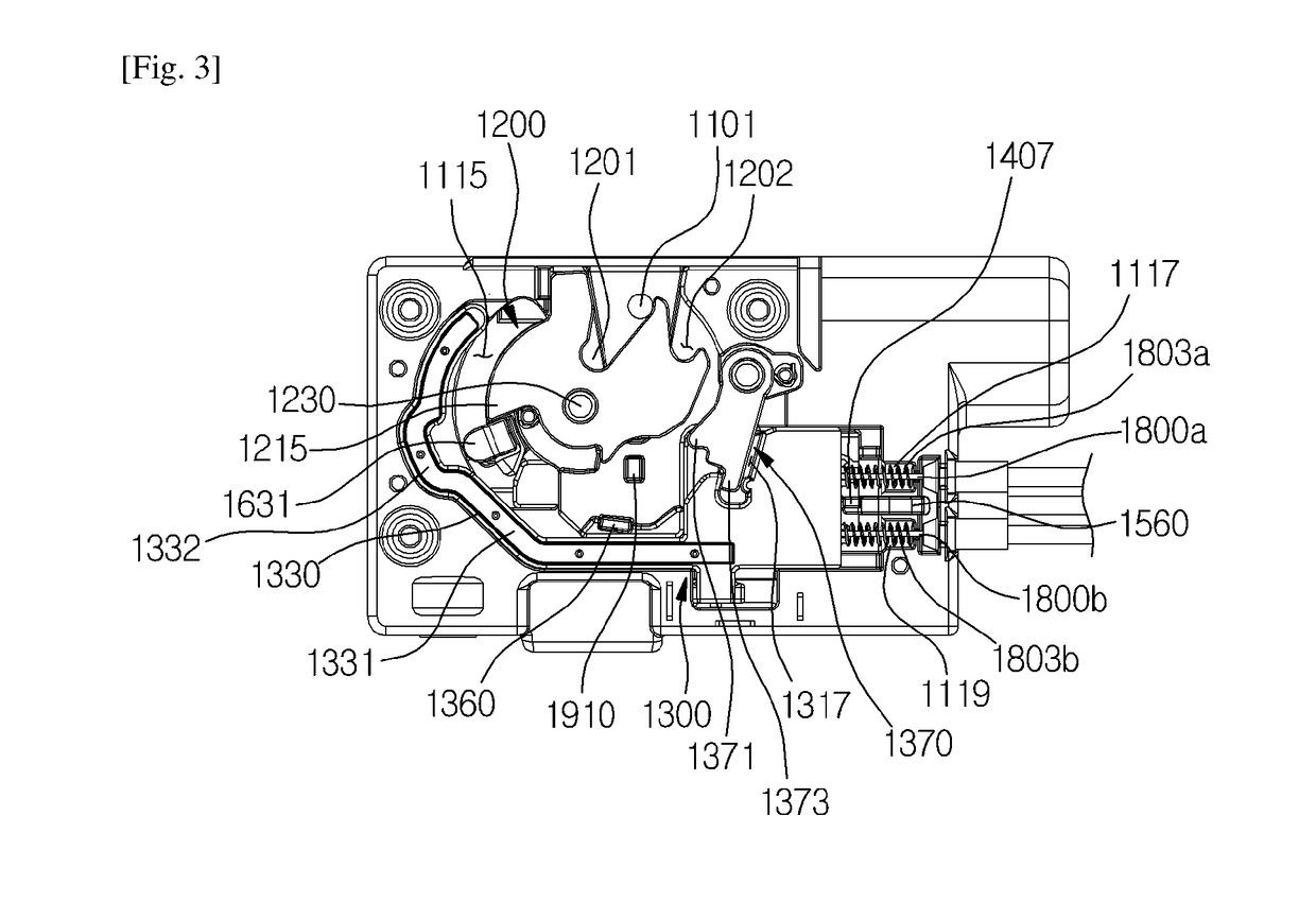
[0117]As illustrated in FIGS. 1 to 45, a vehicle door latch system according to the first exemplary embodiment is characterized in that and comprises: a housing 1100; a latch 1200 rotatably installed in the housing 1100; a door closing member installed in the housing and locking the latch, wherein the door closing member comprises a sliding member slidingly installed in the housing 1100, wherein the sliding member comprises: a main locking member 1300 locking the latch 1200; and a sub-locking member 1400 disposed in one side of the main locking member 1300; a connecting means for sliding both of the main locking member 1300 and the sub-locking member 1400, or sliding only the sub-locking member 1400; a child locking member 1700 slidingly installed in the housing 1100 wherein as the child locking member 1700 is moved, the connecting means is moved so that the main locking member 1300 and the sub-locking member 1400 are slided together, or only the sub-locking member 1400 is slided; a...

embodiment 2

[0619]In describing the vehicle door latch system according to the second exemplary embodiment of the present invention, same symbols will be used for the same or similar elements as those of the vehicle door latch system according to the first exemplary embodiment of the present invention, and the detailed description and illustration will be omitted.

[0620]As illustrated in FIG. 46, the vehicle door latch system according to the second exemplary embodiment is characterized in that the lock-releasing cable connecting portion is formed at the left side of the locking plate, and the lock-releasing cable 2810 which is in the opposite direction of the door lever connecting portion 2800 is withdrawn to the left side of the housing 2100.

[0621]The knob 6 disposed close to the window of the door 1 is directly connected to the lock-releasing cable 2810.

[0622]Even in such case, by extending the lock-releasing cable 2810 long in length the motor 2610 can be installed in the door so as to be di...

embodiment 3

[0623]In describing the vehicle door latch system according to the third exemplary embodiment of the present invention, same symbols will be used for the same or similar elements as those of the vehicle door latch system according to the first and second exemplary embodiments of the present invention, and the detailed description and illustration will be omitted.

[0624]As illustrated in FIGS. 47 to 51, the vehicle door latch system according to the third exemplary embodiment is characterized in that and comprises: a locking member spring 3760 applying an elastic force to a child locking member 3700 in the opposite direction of an external force when the child locking member 3700 is moved by the external force; a locking guide member 3790 rotatably installed in any one of the housing and the child locking member 3700; and a cam-part 3780 formed in the remaining one and guiding the locking guide member 3790 and formed with a stopping slot 3786.

[0625]In the present exemplary embodiment,...


PUM


Abstract

The present invention relates to a vehicle door latch system, more particularly, relates to a vehicle door latch system comprising: a locking member spring applying an elastic force to the locking member in the opposite direction of an external force when the locking member is moved by the external force; a locking guide member rotatably installed in a housing; and a cam-part formed in a locking member for guiding the locking guide member and formed with a stopping slot; so that the structure of the device becomes simple, and at the same time, releasing of the locking member is prevented when the latch is rotated by the main gear even when the locking member is moved by the same main gear used for the latch.

Description

TECHNICAL FIELD[0001]The present invention relates to a vehicle door latch system, more particularly, relates to a vehicle door latch system comprising a locking member spring applying an elastic force to the locking member in the opposite direction of an external force when the locking member is moved by the external force, a locking guide member rotatably installed in a housing, a cam-part formed in a locking member for guiding the locking guide member and formed with a stopping slot.BACKGROUND ART[0002]Generally, a vehicle door latch system is used for opening and closing the automobile's door or locking or lock-releasing thereof, as suggested in Korea Patent No. 0535053.[0003]However, such vehicle door latch system of the prior art has a problem wherein an unnecessary force is applied to the various components such as a latch connected to the door lever and the like when the door lever is pulled while the door is being locked, therefore, damages in the various components of the ...

Claims


Application Information

Patent Timeline
IPC IPC(8): E05B81/14E05B77/26E05B79/20E05B81/06E05B81/36E05B81/66
CPCE05B81/14E05B77/26E05B79/20E05B81/06E05B81/36E05B81/66E05B77/54E05B81/34E05B85/02E05B85/08E05B81/64E05B81/72
Inventor JEONG, HAE IL
Owner WOOBO TECH
Why Eureka
Try Eureka