Tillage shank with adjustable depth fertilizer tube

a fertilizer tube and depth adjustment technology, applied in the field of tillage equipment, can solve the problems of time-consuming and difficult adjustment, and achieve the effect of minimizing abrasion wear and quick and convenient adjustment of depth

Active Publication Date: 2011-01-11
KUHN KRAUSE
View PDF12 Cites 12 Cited by
  • Summary
  • Abstract
  • Description
  • Claims
  • Application Information

AI Technical Summary

Benefits of technology

[0004]Accordingly, an important object of the present invention is to provide a way of quickly and conveniently adjusting the depth of the one or more delivery tubes relative to the shank which carries it. Another important object of the invention is to provide the desired convenience and speed of adjustment while maintaining the one or more fertilizer tubes in protected positions on the shank so as to minimize abrasive wear on the tube as the shank assembly moves through the soil.

Problems solved by technology

A problem with the welded-on design is that if the farmer desires to apply fertilizer at different depths in varying conditions, he must change the depth of the shank as well, whether changing the shank depth is optimum for the situation at hand or not.
Some commercially available conventional units provide fertilizer tubes that can be adjusted relative to the shank, but such adjustments are difficult to make and time-consuming.

Method used


Image

  • Tillage shank with adjustable depth fertilizer tube
  • Tillage shank with adjustable depth fertilizer tube
  • Tillage shank with adjustable depth fertilizer tube

Examples


Embodiment Construction

[0014]The present invention is susceptible of embodiment in many different forms. While the drawings illustrate and the specification describes certain preferred embodiments of the invention, it is to be understood that such disclosure is by way of example only. There is no intent to limit the principles of the present invention to the particular disclosed embodiments.

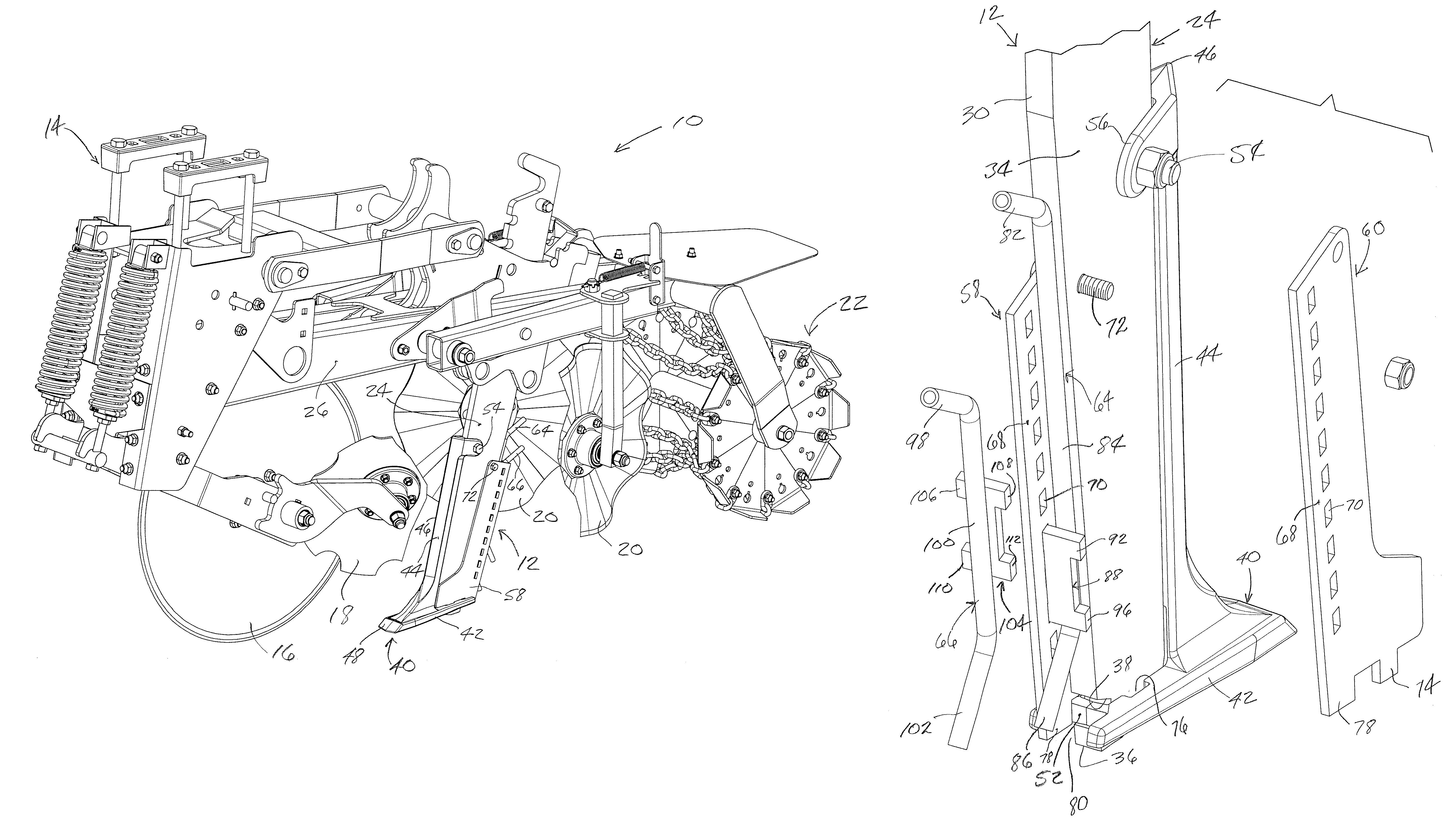
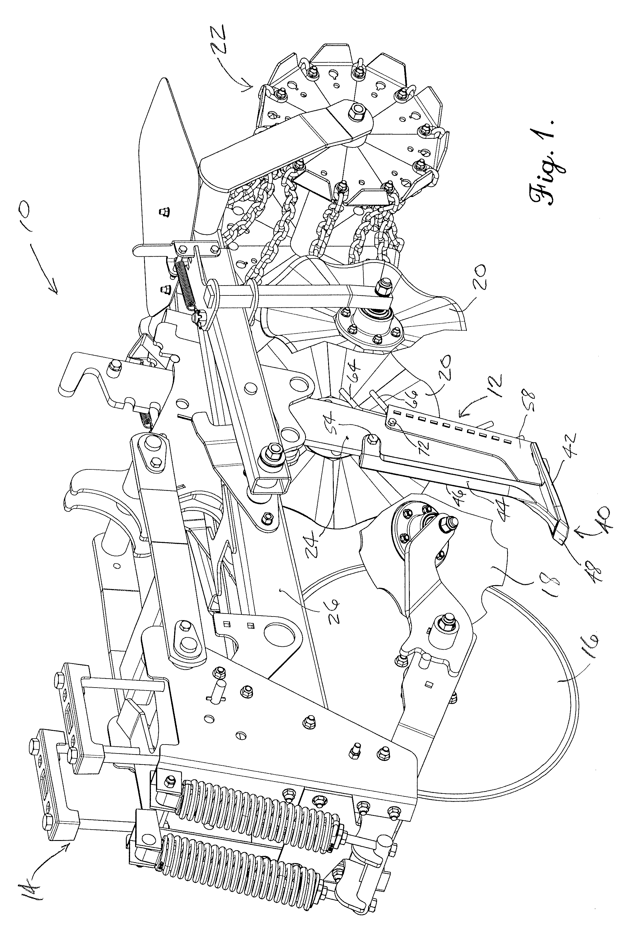
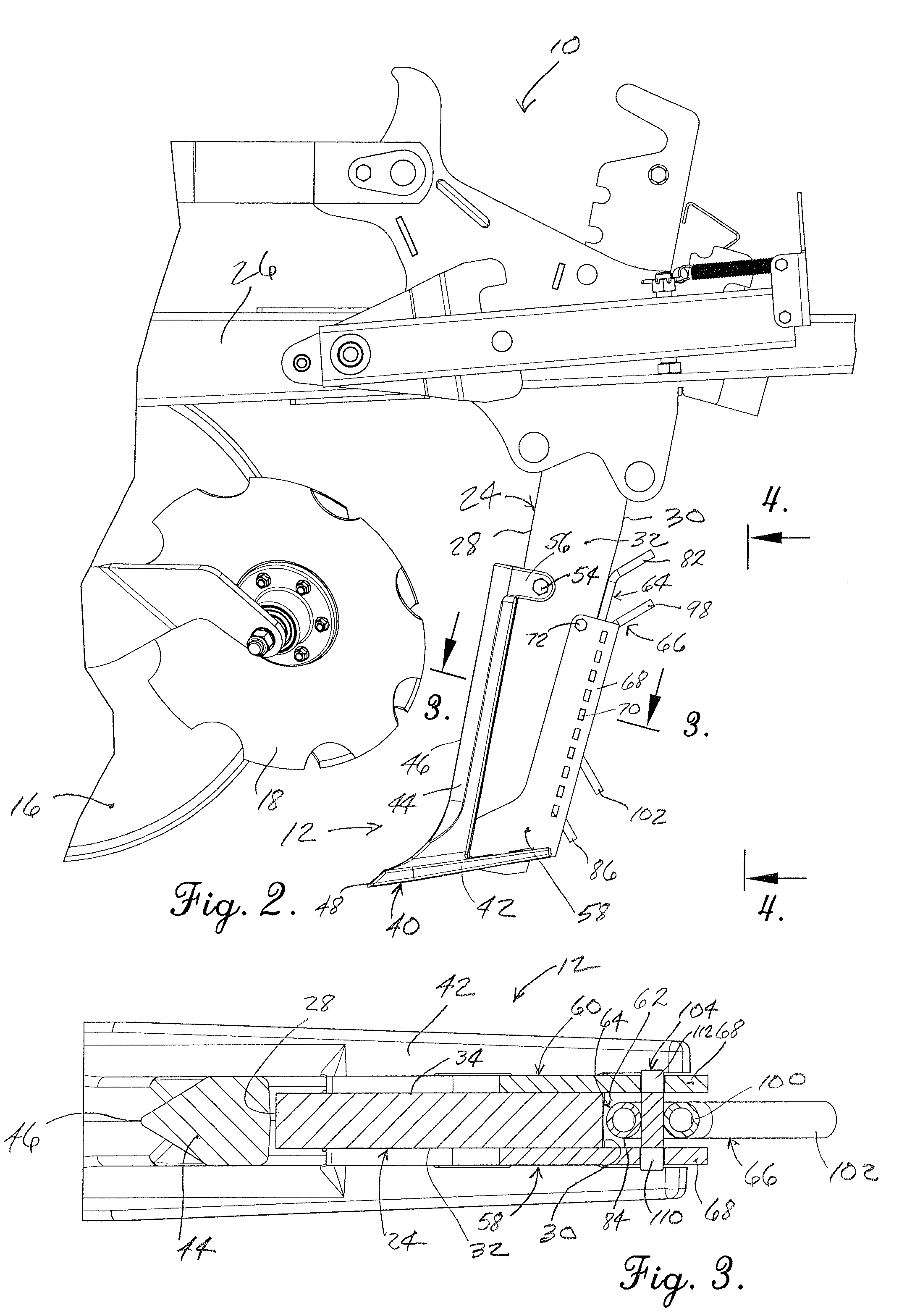
[0015]The tillage device 10 of FIG. 1 has been selected for purposes of illustration only and is not to be considered limiting insofar as the scope of the present invention is concerned. In the illustrated embodiment, device 10 comprises a row unit that is particularly adapted for strip till applications in which a relatively narrow strip of soil is tilled and a berm is created for subsequently receiving planted seeds. In the context of the present invention, tillage device 10 includes a special shank assembly 12 having one or more depth-adjustable delivery tubes as hereinafter explained in more detail.

[0016]Generally ...


PUM


Abstract

A tillage shank assembly has one or more substance delivery tubes supported along the back edge of the generally upright shank of the assembly. A pair of side plates on opposite sides of the shank have rear margins that project rearwardly beyond the rear edge of the shank to define a protective gap within which the tubes are disposed. Laterally extending projections on the tubes are received within selected ones of a vertical series of holes in the side plates, depending upon the desired depth for the tubes. By temporarily removing a bolt that attaches the tops of the side plates to the shank, the side plates may be separated sufficiently to permit the projections of the tubes to be withdrawn from their current holes and reinserted into other holes to change their vertical locations. Replacing the bolt and tightening it down returns the side plates to their working positions.

Description

TECHNICAL FIELD[0001]The present invention relates to tillage equipment and, more particularly, to a tillage shank assembly having one or more substance delivery tubes that may be depth-adjusted relative to the shank of the assembly to correspondingly adjust the depth at which a substance such as fertilizer may be deposited below the surface of the ground.BACKGROUND AND SUMMARY[0002]Tillage shanks are sometimes provided with a delivery tube for the purpose of placing fertilizer or other substance below the surface of the ground at the same time the moving shank is cutting through and working the soil. Some commercially available shank assemblies include a tube that has been permanently welded to the shank at a fixed location. In other situations, the farmer may obtain tubes separately from the shanks and then weld the tubes to the shanks.[0003]A problem with the welded-on design is that if the farmer desires to apply fertilizer at different depths in varying conditions, he must chan...

Claims


Application Information

Patent Timeline
Patent Type & Authority Patents(United States)
IPC IPC(8): A01C7/00
CPCA01C5/062A01C7/203
Inventor ANKENMAN, THOMAS W.
Owner KUHN KRAUSE
Why Eureka
Try Eureka