Self regulating fluid bearing high pressure rotary nozzle with balanced thrust force

a self-regulating, rotary nozzle technology, applied in the direction of engine seals, cleaning processes and apparatuses, cleaning using liquids, etc., can solve problems such as unsatisfactory adaptation, achieve the effect of reducing the number of parts, facilitating economical manufacture and replacement of wearable parts, and simplifying the configuration of moving parts

Active Publication Date: 2009-12-22
STONEAGE
View PDF7 Cites 15 Cited by
  • Summary
  • Abstract
  • Description
  • Claims
  • Application Information

AI Technical Summary

Benefits of technology

[0003]It has generally been considered desirable to keep the diameter of any rotating portions of a nozzle smaller than the largest diameter of such a nozzle so that contact between the rotating portions and any surface being cleaned is minimized thereby minimizing abrasive wear to the nozzle and interference with the rotational movement of the nozzle jets. Other prior art devices have used nozzles which rotate around a central tube which provides the liquid source. However for the aforementioned reason, such devices, while being able to provide a cylindrical path of coverage with their rotating bodies, have not been well adapted to both providing a rotating coverage which can include a path very close to the rotational axis of the device and an “straight-through” liquid path.
[0014]A further object of the invention is to provide a rotating nozzle for use with a high pressure liquid in which jet heads of varying configurations are readily interchangeable.

Problems solved by technology

However for the aforementioned reason, such devices, while being able to provide a cylindrical path of coverage with their rotating bodies, have not been well adapted to both providing a rotating coverage which can include a path very close to the rotational axis of the device and an “straight-through” liquid path.

Method used


Image

  • Self regulating fluid bearing high pressure rotary nozzle with balanced thrust force
  • Self regulating fluid bearing high pressure rotary nozzle with balanced thrust force
  • Self regulating fluid bearing high pressure rotary nozzle with balanced thrust force

Examples


Embodiment Construction

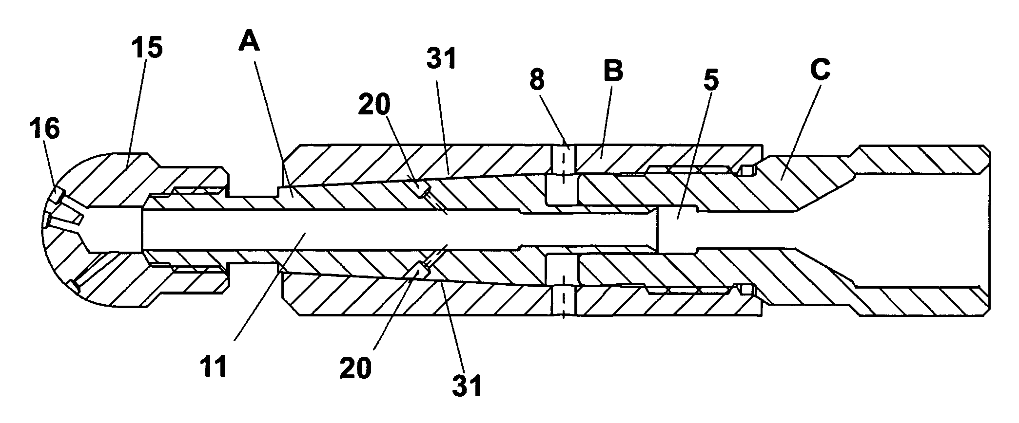
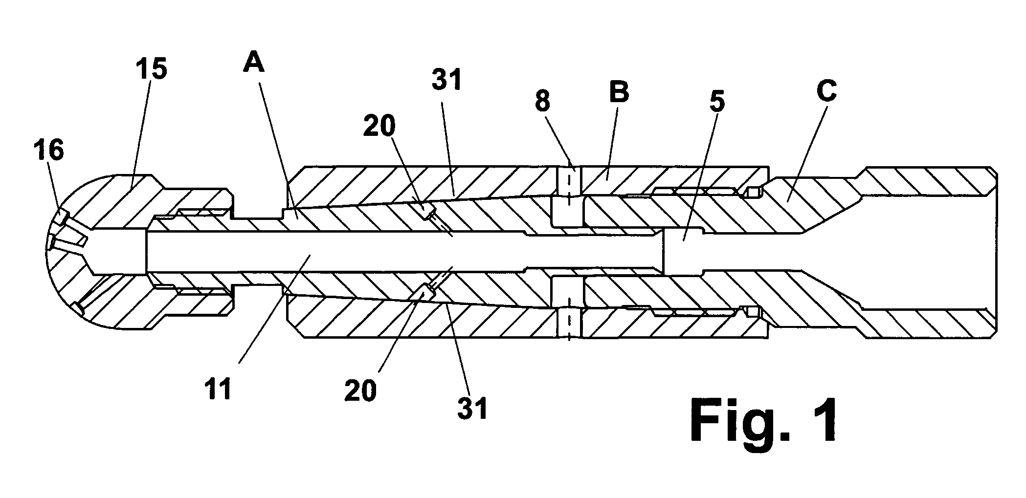
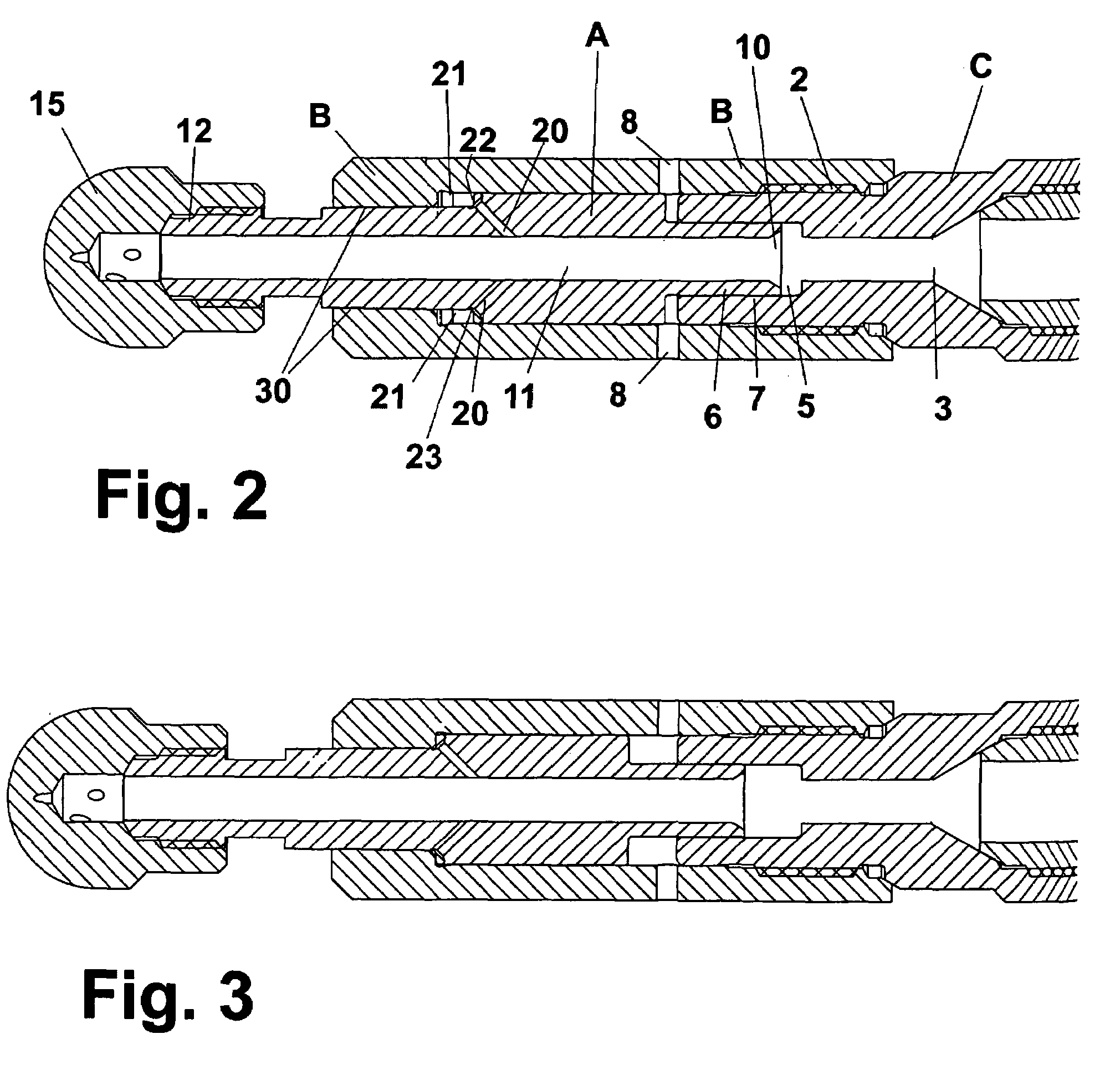
[0019]As can be seen most clearly in FIG. 2, the present invention allows a simple three-piece rotary nozzle structure. A hollow cylindrical rotary shaft A is contained in a housing or body comprised of an inlet portion C and an outlet portion B. The housing portions are secured together and sealed using threading or other similar fastening means 2 which allows assembly and disassembly of the device including allowing shaft A to be really inserted or removed. The inlet portion C provides an inlet 3 for high-pressure liquid fed to the device by hose or other similar means attached to the inlet by any suitable means, most commonly a mated threaded fitting. A suitable material for each of the nozzle portions will have fairly high strength and resistance to galling, for example, any of various high nickel stainless steels. A surface treatment or plating may be used for any known benefits such as lubricity or abrasion resistance.

[0020]At the opposite end of the housing inlet portion is a...


PUM


Abstract

A high pressure rotary nozzle having a rotating shaft operating within a fixed housing wherein the of axial force which acts upon the shaft due to the liquid pressure at the shaft inlet is balanced by allowing passage of a small amount of the pressurized liquid to be bled to an area or chamber between the outside of the opposite end of the shaft and the inside of the housing where the liquid pressure can act axially in an opposing direction upon the shaft to balance the axial inlet force. The balance of axial forces is self-regulating by controlling escape of the liquid through a tapered or frusto-conical region between the shaft and housing. This further provides a liquid bearing between the two surfaces and allows use of interchangeable rotating jet heads having jet orifices which can be oriented in virtually any desirable configuration including axially forward of the nozzle.

Description

BACKGROUND OF THE INVENTION[0001]The present invention provides a simplified and reliable construction for a high-pressure rotating water jet nozzle which is particularly well suited to industrial uses where the operating parameters can be in the range of 1,000 to 40,000 psi, rotating speeds of 10,000 rpm or more and flow rates of 2 to 50 gpm. Under such use the size, construction, cost, durability and ease of maintenance for such devices present many problems. Combined length and diameter of such devices may not exceed a few inches. The more extreme operating parameters and great reduction in size compound the problems. Pressure, temperature and wear factors affect durability and ease of maintenance and attendant cost, inconvenience and safety in use of such devices. Use of small metal parts and poor quality of materials in such devices may result in their deterioration or breakage and related malfunctioning and jamming of small spray discharge orifices or the like. The present inv...

Claims


Application Information

Patent Timeline
Patent Type & Authority Patents(United States)
IPC IPC(8): B05B3/06B05B3/02F16J15/34B08B3/00
CPCB05B3/06B05B3/002B05B15/18
Inventor WRIGHT, DOUGLAS E.WOLGAMOTT, JOHN E.
Owner STONEAGE
Why Eureka
Try Eureka