Interchangeable choke assembly

a technology of interchangeable choke and assembly, which is applied in the direction of mechanical equipment, sealing/packing, and borehole/well accessories, etc., can solve the problems of large failure of the flow reducer itself, slow and continuous loss of desired operating pressure, and severe wear of the metal housing surrounding the flow reducer, so as to reduce the pressure in the exit piping and prolong the operating life , the effect of minimizing abrasion wear

Inactive Publication Date: 2005-05-17
CARPENTER ADVANCED CERAMICS
View PDF16 Cites 14 Cited by
  • Summary
  • Abstract
  • Description
  • Claims
  • Application Information

AI Technical Summary

Benefits of technology

[0006]In a first aspect of the present invention, a pressure reducing device is provided that has an extended operating life. The internal components of the device are made entirely of ceramic materials that minimize abrasive wear caused by sand and other debris in oil. In one embodiment of the invention, a fixed choke is provided to reduce pressure in the exit piping of an oil line. The device has a hollow body having an inlet opening, an outlet opening and a central flow channel between the inlet opening and the outlet opening. A first liner is disposed in the inlet opening, and a second liner is disposed in the outlet opening. An outer sleeve is disposed in the central flow chamber and cooperates with an inner sleeve having an orifice. The inner sleeve is interchangeable with other sleeves having different orifices to modify the pressure and flow of oil as it is discharged from the device to oil processing equipment.

Problems solved by technology

The abrasive oil-and-sand mixture not only wears away the inside wall of the flow channels, but also backwashes around the outside diameter of the flow reducer and wears away the steel body of the flow reducer, resulting in gross failure of the reducer itself.
Often, the metal housing surrounding the flow reducer is severely worn as well.
Continuous erosion of the pressure reducer over time results in a slow and continuous loss of desired operating pressure until gross failure requires replacement.
This loss in operating pressure causes an ever-increasing sand content, resulting in less efficient oil production.
Since high pressure oil wells typically produce about 5,000 to 12,000 barrels of oil a day, the downtime associated with replacement of a pressure reducer can result in a significant loss of oil production.

Method used


Image

  • Interchangeable choke assembly
  • Interchangeable choke assembly
  • Interchangeable choke assembly

Examples


Embodiment Construction

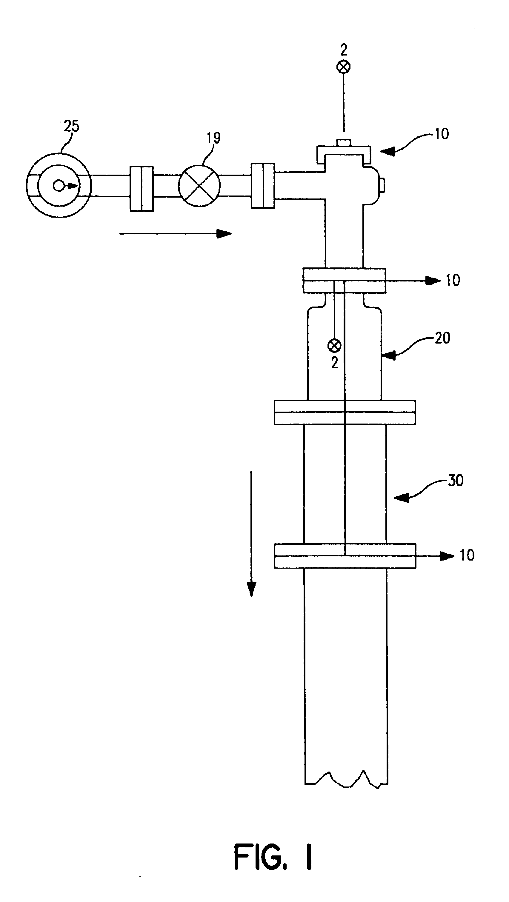
[0033]Referring now to the drawings wherein like reference numerals indicate identical or corresponding parts among the several views and in particular to FIG. 1, there is shown a pressure reducing assembly for a high-pressure well head. For purposes of orientation, the oil flow originating from the well flows through the pressure reducing assembly according to the present invention and toward the oil process piping in the direction shown by the arrows. A pressure reducing valve 10 is connected through an isolation valve 19 to a well head manifold 25. The downstream side of pressure reducing valve 10 is connected to a first spool adapter 20, which is connected to a second spool adapter 30. The second spool adapter 30 is connected to the piping that leads to the oil processing facilities (not shown).

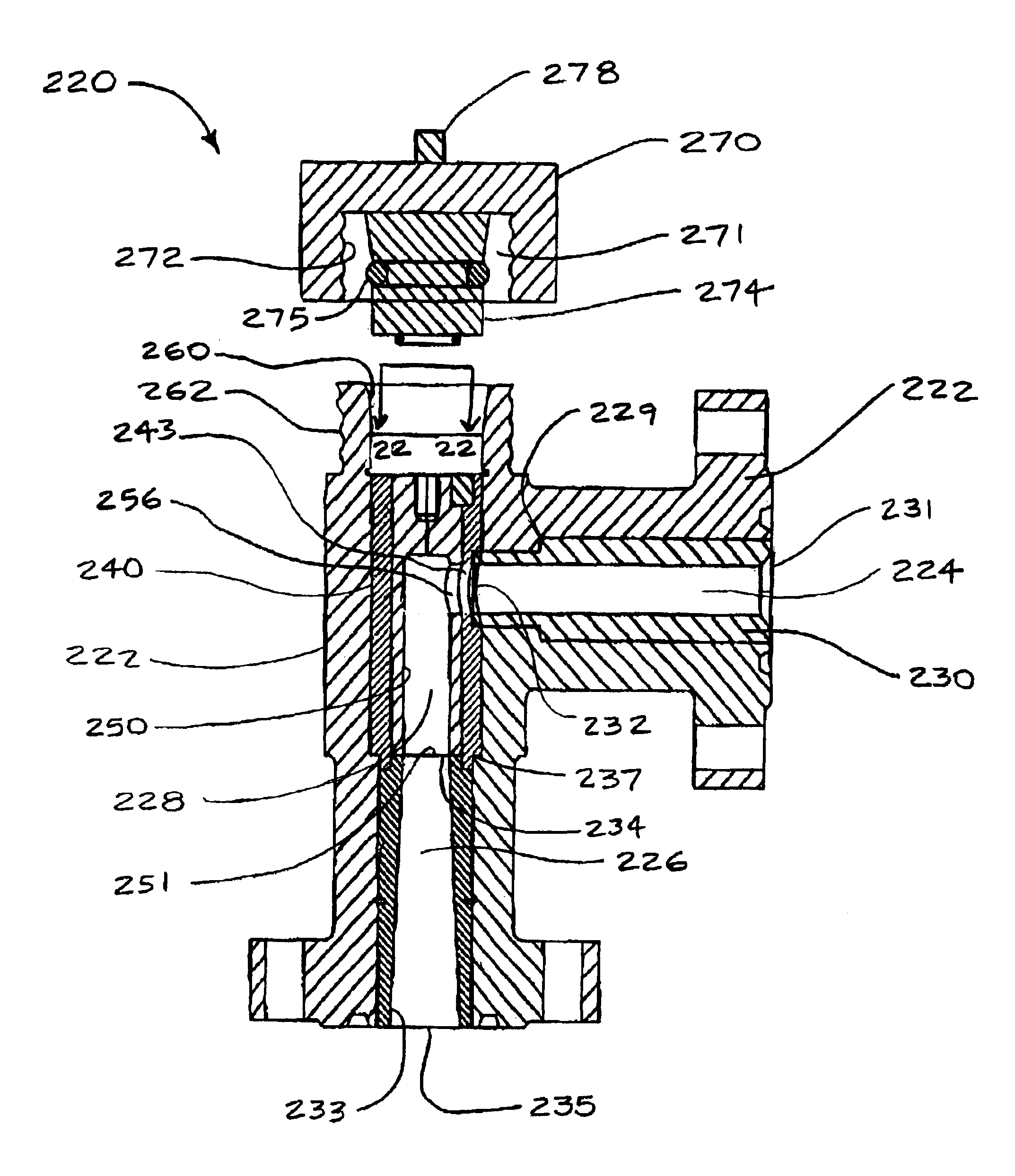
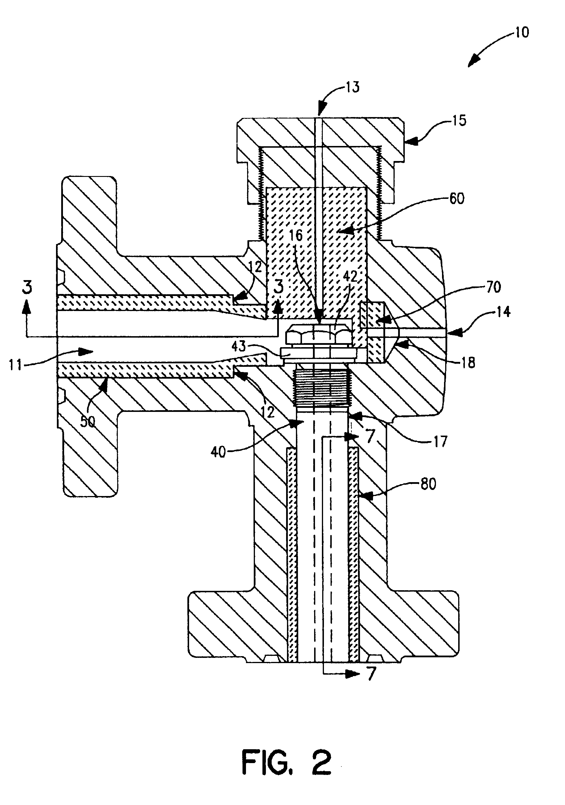
[0034]Referring now to FIG. 2, the pressure reducing valve 10 has a metallic body that includes an upstream channel 11, a direction-changing cavity 16, a downstream channel 17, and a key-...


PUM


Abstract

A pressure reducing apparatus and a method of operating a pressure reducing apparatus are provided. The apparatus is operable to reduce the pressure and flow rate of oil being discharged from a well head to downstream processing equipment. The device has central flow channel configured to receive a flow of oil and reduce the pressure in the oil. The apparatus has internal components formed of a ceramic material that resists erosion and wear caused by sand and other debris in the oil. In one embodiment of the invention, a ceramic outer sleeve is disposed in the central flow channel and cooperates with a ceramic inner sleeve having an orifice. The ceramic inner sleeve is interchangeable with other ceramic sleeves having different orifices to modify the pressure and flow characteristics of oil as it is discharged to the downstream processing equipment.

Description

RELATED APPLICATIONS[0001]This application is a CIP of Ser. No. 10 / 130,651 now U.S. Pat. No. 6,662,869 filed May 20, 2002 claims priority under 35 U.S.C. §120 from U.S. application Ser. No. 10 / 130,651, filed as International Application No. PCT / US00 / 32150 on Nov. 28, 2000, which is hereby incorporated herein by reference.FIELD OF THE INVENTION[0002]This invention relates generally to flow components for high pressure oil wells, and in particular to the use of ceramic material in wear components for a pressure reducer assembly for such wells.BACKGROUND[0003]Many oil well facilities around the world operate under high pressure. In other words, the pressure within the well is sufficiently high (e.g., 3000 to 5000 psi) to carry the crude oil to the surface without pumping. Unless restricted, the crude oil flows to the surface at a high velocity and contains sand and other debris which erodes the interior surfaces of the oil well piping components. In order to limit the amount of sand an...

Claims


Application Information

Patent Timeline
Patent Type & Authority Patents(United States)
IPC IPC(8): E21B34/00E21B34/02E21B43/12
CPCE21B43/12E21B34/02
Inventor MENTESH, IBRAHIM M.BAENZIGER, CARL R.THURSFIELD, GAVIN S.THOMPSON, STEVEN W.
Owner CARPENTER ADVANCED CERAMICS
Why Eureka
Try Eureka