Method and apparatus for increasing transmission capacity in optical transport network

a technology of optical transport network and transmission capacity, applied in data switching networks, multiplex communication, wavelength-division multiplex systems, etc., can solve the problems of chromatic dispersion, otn receives, and the method is disadvantageous for chromatic dispersion, and achieves the effect of increasing the transmission capacity of the optical network

Inactive Publication Date: 2011-01-11
ELECTRONICS & TELECOMM RES INST
View PDF12 Cites 4 Cited by
  • Summary
  • Abstract
  • Description
  • Claims
  • Application Information

AI Technical Summary

Benefits of technology

[0034]According to another aspect of the present invention, there is provided a method of increasing transmission capacity in an optical network, the method including (a) mapping and framing an input signal to an OTH signal by using a VC method, converting the OTH signal into a plurality of multi-wavelength optical signals, and transmitting an optical signal by multiplexing; and (b) demultiplexing the optical signal, converting each of the demultiplexed wavelength optical signals into electric signals, and restoring the input signal by extracting a frame and de-mapping.

Problems solved by technology

Although increasing speed per channel by using the above-described method may easily increase transmission speed, the method is disadvantageous for chromatic dispersion, Polarization Mode Dispersion (PMD), and non-linearity in an optical fiber.
A problem with this method is that the OTN receives a tributary signal including not only OTH signals but also signals from various types of networks.
Thus, if all 40 G signals are transmitted through one channel, various additional compensating devices are required because of the above-described problem where the 40 G signal has to be received as a tributary signal from the beginning, so that the cost for the entire system will be increased and a system will become complicated.
When transmitting by using the VC method, data is loaded into 2 different frames and transmitted individually through each network, and therefore a time delay between the frames will occur.
Also, transmitting such a high speed signal causes problems in optical fiber transmission and electric signal transmission.
However, although it is very easy to serialize signals when receiving the signals if the original signal is multiplexed at a low speed, a problem occurs when making frames which were originally at a high speed be in parallel.
However, if the 40 G signal is one data frame such as a SDH Synchronous Transport Module (STM)-256 signal from the beginning, a problem occurs when making the signal into 16 parallel channels.
Also, another method of increasing the capacity includes a method of increasing a number of 2.5 G ports, but a problem occurs in that a back plane layout becomes complicated.
Also, it is difficult to obtain reliable formation up to 10 G because of a difficulty in employing the optical line in the PCB.

Method used


Image

  • Method and apparatus for increasing transmission capacity in optical transport network
  • Method and apparatus for increasing transmission capacity in optical transport network
  • Method and apparatus for increasing transmission capacity in optical transport network

Examples


Embodiment Construction

[0048]The attached drawings illustrate exemplary embodiments of the present invention, and are referred to in order to gain a sufficient understanding of the present invention and its merits and objectives.

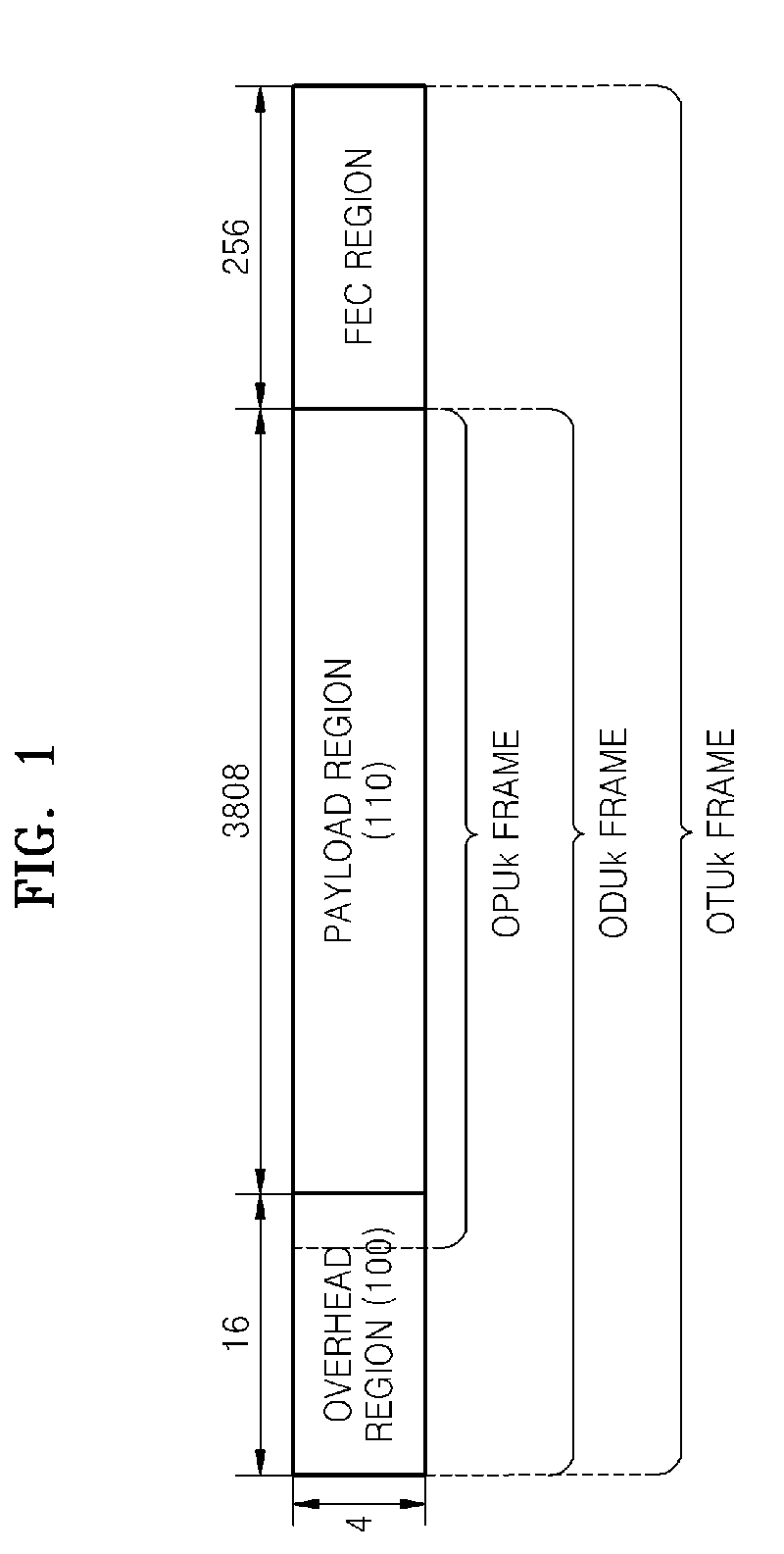
[0049]FIG. 1 illustrates a structure of an Optical channel Data Unit-k (ODUk) frame.

[0050]In order to understand a basic structure of a signal frame for Optical Transport Hierarchy (OTH) signal transmission, a concept of a payload and an overhead should be understood.

[0051]In order to transmit various types of tributary signals through an optical channel, a signal that is to be transmitted should be appropriately converted. Parts used for conversion include a payload 110 which is data of a tributary signal that is being carried, and an overhead 100 which employs various types of information about the payload and is transmitted through the optical channel. In other words, the overhead 100 carries information about a type of a payload for each section, a structure, a start point, an...


PUM


Abstract

Provided are a method and apparatus for increasing transmission capacity for large-capacity high-speed signal transmission in an optical transport network (OTN). A method and apparatus for increasing transmission capacity are needed, which can transmit a large-capacity high-speed signal in order to transmit a signal through a united OTN by adapting signals from various tributary signal networks which have been independently operated for voice, image, or data transmission. Although various types of techniques such as Time Division Multiplexing (TDM), Wavelength Division Multiplexing (WDM), and an optical Printed Circuit Board (PCB) method have been performed, the techniques have various limitations. Therefore, a method and apparatus is provided for embodying a large-capacity optical transmission network, which overcome the limitations by using a Virtual Concatenation (VC) method.

Description

CROSS-REFERENCE TO RELATED PATENT APPLICATION[0001]This application claims the benefit of Korean Patent Application No. 10-2006-0122638 filed on Dec. 5, 2006 and Korean Patent Application No. 10-2007-0033348 filed on Apr. 4, 2007 in the Korean Intellectual Property Office, the disclosures of which are incorporated herein in their entirety by referenceBACKGROUND OF THE INVENTION[0002]1. Field of the Invention[0003]The present invention relates to large-capacity high-speed signal transmission in an optical transport network (OTN), and more particularly, to a method and apparatus for increasing a transmission capacity for an embodiment of a large-capacity back plane in an OTN.[0004]2. Description of the Related Art[0005]Existing various networks support various types of signal frames, transmission speeds, or multiplexing methods that are different from each other. Although conventional networks used to be independently operated, forming various types of technology fields and markets fo...

Claims


Application Information

Patent Timeline
Patent Type & Authority Patents(United States)
IPC IPC(8): H04J14/02
CPCH04J3/1652H04J14/02H04J3/1658H04J3/167H04J2203/0094
Inventor CHO, HYUNWOOKANG, SAE KYOUNGSHIN, JONG-YOONKO, JE SOO
Owner ELECTRONICS & TELECOMM RES INST
Why Eureka
Try Eureka