
Converting a corn head row unit for harvesting corn stalks in addition to ears

a corn head and corn head technology, applied in the field of corn head row unit conversion, can solve the problems of inconvenient corn harvesting and substantial additional cost of corn head addition,

Inactive Publication Date: 2011-01-25
DEERE & CO
View PDF43 Cites 62 Cited by
  • Summary
  • Abstract
  • Description
  • Claims
  • Application Information

AI Technical Summary

Benefits of technology

Enables efficient collection of corn stalks and ears using a single header, reducing operational costs and improving harvesting efficiency by allowing for seamless transition between ear-only and stalk-and-ear harvesting modes.

Problems solved by technology

While the row units of conventional combine harvesters for harvesting soy beans, milo or sunflowers are equipped with cutter arrangements for severing the stalks from the ground and with gathering devices including a grasping characteristic for grabbing the plant stalks and guiding the latter into cross-conveyors for narrowing the flow of crop to a width commensurate with that of a combine feeder house, these row units are not supplied with snapping rolls, and thus are not suitable for harvesting corn in situations where it is not desired to convey the entire stalk into the combine.
Certainly it would be conceivable to construct a corn head for a combine with row units similar to those used for forage: harvesters, where a cutter or cutters is provided for cutting the corn stalks from the ground, but this would require one header to, be provided when it is desired to harvest only the ears and a completely separate header to be provided when it is desired to harvest stalks along with the ears, with the additional header being a substantial additional cost.

Method used


Image

  • Converting a corn head row unit for harvesting corn stalks in addition to ears
  • Converting a corn head row unit for harvesting corn stalks in addition to ears
  • Converting a corn head row unit for harvesting corn stalks in addition to ears

Examples


Embodiment Construction

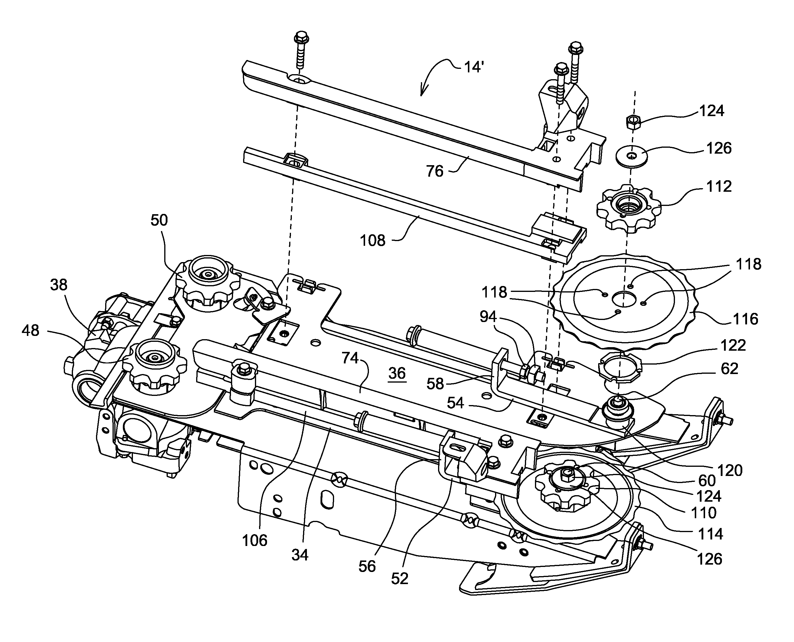
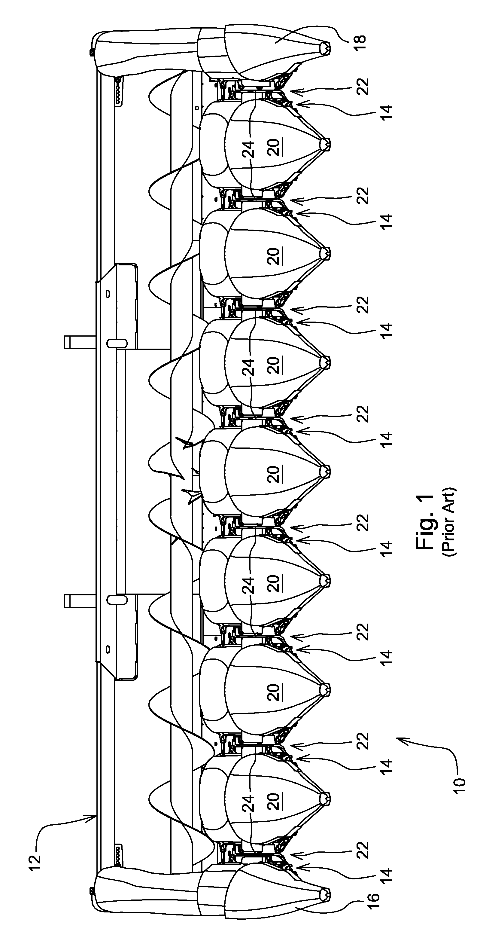
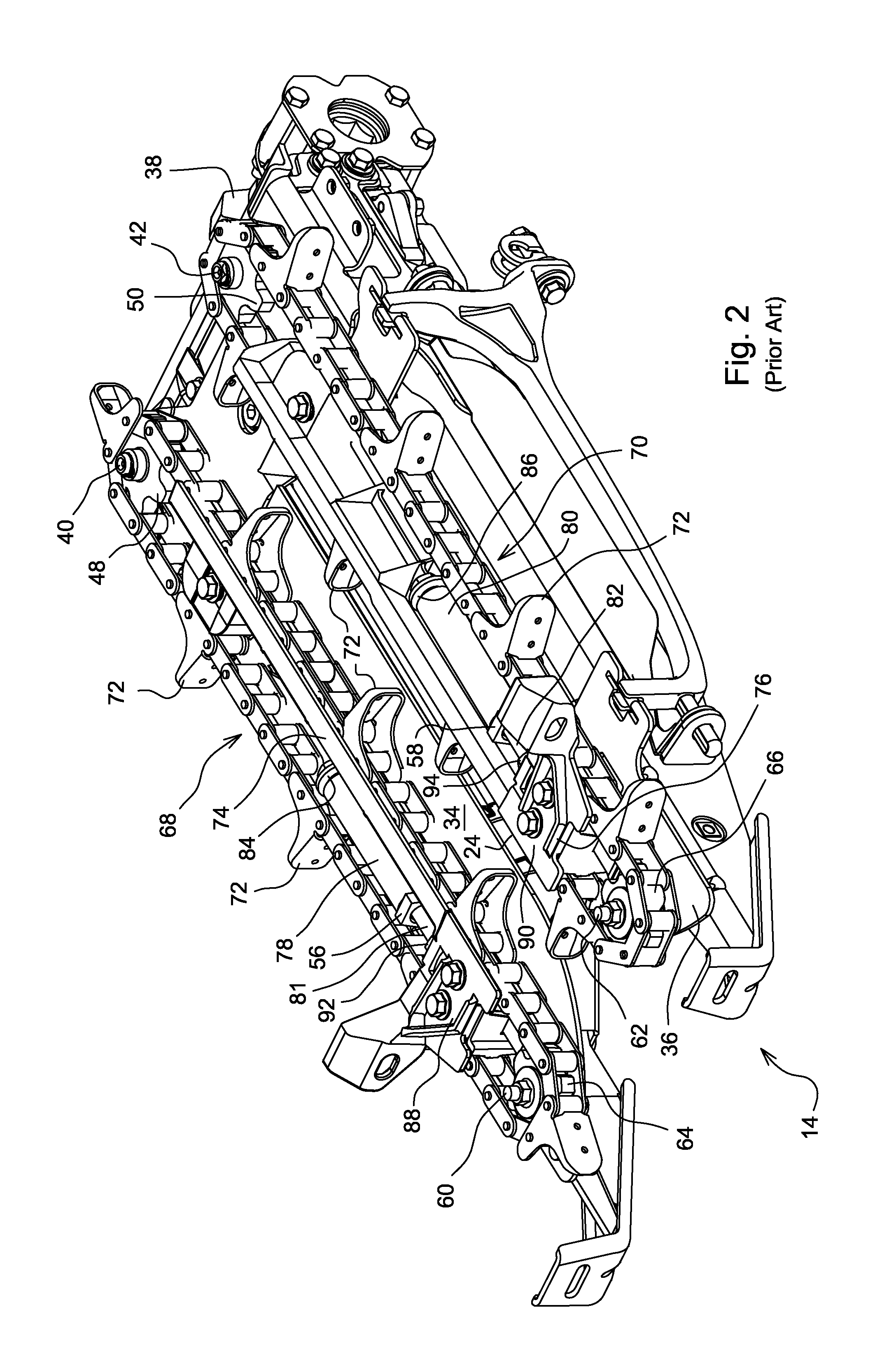
[0017]Referring now to FIG. 1, there is shown a corn head 10 including a transversely extending frame 12 across the width of which is attached a plurality of forwardly projecting row units 14 spaced in side-by-side relationship to each other a distance commensurate with that of the spacing between adjacent rows of corn to be harvested, with it being noted that it is conventional to mount the row units 14 for transverse adjustment in order to accommodate various corn row spacings. Mounted to the row units 14 and serving to separate comingled stalks of adjacent rows from one another are crop dividers including right and left dividers 16 and 18, respectively, at the opposite ends of the corn head 10, and seven identical central dividers 20, with the crop dividers defining longitudinal passages 22 between them which are centered relative to rows to be harvested and relative to a central fore-and-aft extending relatively narrow throat 24 defined by each row unit 14, as described below in...


PUM


Abstract

Each row unit of a corn head can easily be converted between a first mode, wherein only ears are harvested, and a second mode, wherein ears together with stalks are harvested. In the first mode, a pair of snapping rolls is mounted for operation beneath each row unit frame for grasping corn stalks and pulling them downwardly through a narrow throat defined by a pair of laterally adjustable deck plates mounted to a top surface of the row unit frame. In the second mode, the snapping rolls are either removed or disabled and at least one stalk cutting disk is mounted on one of a pair of gathering chain drive idler shafts, mounted at the forward end of the row unit frame, for rotating above the frame. The snapping rolls are disabled by adjusting the deck plates toward each other to close the throat.

Description

FIELD OF THE INVENTION[0001]The present invention relates to a row-crop combine harvester, and, more particularly, relates to a row unit arrangement for a corn head for such a harvester.BACKGROUND OF THE INVENTION[0002]Recently, designers have constructed row-crop combine harvesters so as to be able to collect a desired amount of crop residue (crop material other than grain) so that this residue can be used for conversion into fuel. However, during the normal process of harvesting corn, most of the stalk is left on the ground with the ears being removed from the stalk using snapping rolls and sent on into the separator and cleaning arrangements where kernels of corn are removed from the cob and other crop residue. U.S. Pat. No. 5,878,561 discloses a row crop harvester of this type. Recovering the stalk material left on the ground has required separate operations, for example, the use of a rotary cutter to sever the stalks from the ground and form a windrow, and the use of a baler to...

Claims


Application Information

Patent Timeline
Patent Type & Authority Patents(United States)
IPC IPC(8): A01D45/02
CPCA01D45/023
Inventor HOFFMAN, DANIEL STEPHEN
Owner DEERE & CO
Learn More