Cinching loop

a loop and loop technology, applied in the field of clamping loops, can solve the problems of increasing the overall time of the operation, affecting the overall efficiency of the operation, so as to limit the flow of blood and reduce the complexity

Inactive Publication Date: 2011-01-25
SUB Q
View PDF240 Cites 91 Cited by
  • Summary
  • Abstract
  • Description
  • Claims
  • Application Information

AI Technical Summary

Problems solved by technology

Suturing tissue or organs is a tedious and delicate procedure.
Even after one half-hitch knot is formed and properly cinched, the twisting problem persists and may interfere with, or prevent, the subsequent formation of additional half-hitch knots as would “lock” the suture.
This process is time consuming.
These problems increase the overall time of the operation and contribute undesirably to hand, and overall, surgeon fatigue.
However, the prior apparatuses and associated methods of use provide assistance only in tying relatively simple knots or only small portions of more complicated knots.
The square knot is a simple knot, but difficult to fashion solely with surgical instruments such as are necessary in endoscopic surgical procedures.
However, once formed, the square knot may easily become untied.
Endoscopic and interventional procedures are currently hampered by the inability to easily tie knots within the body and other relatively inaccessible involved spaces. FIG. 1 illustrates a single strand of suture used to seal a blood vessel puncture site.
Furthermore, having the thread near the skin may increase the chance of infection to the patient.
Additionally, the tissue cinching loop 106 may not adequately close the puncture site 110 causing blood to flow out of the blood vessel.
Moreover, the entire suture thread 102 directly contacts the tissue or blood vessel wall 104 which may cause lacerations and tearing of the tissue 104 resulting in additional injury and requiring additional repair to the blood vessel puncture site 110.
The drawbacks of endoscopic and similar surgery are both the distance the suturing site is located inside the body as well as the limited space available within the body since manipulation of the surgical instruments themselves are used for the suturing process.
With respect to the latter, a problem arises in manipulating the curved needle to easily tie a knot to close the surgical incision in situ.
However, significant limitations relating to current apparatuses and methods for the formation of suture knots include: (1) being limited to the formation of simple knots such as the square knot; (2) involving knots which require the manipulation of both ends of a length of suture filament which, accordingly, cannot be substantially tied prior to surgery or merely slipped into place; (3) requiring multiple manipulations outside of the surgical incision with loops thereby formed being afterwards coaxed toward the suture site; and (4) requiring the depression of the skin surface and cutting of excess suture from the body.
However, this introduces other complications.
The problem of thread tangling persists.
Further, the procedure is inherently awkward by requiring that the free ends of the suture projecting away from the loop be held taut as a pusher is pressed through the cannula to reduce the loop diameter.
Further, the thread is prone to escaping from the open free end of the pusher.
This is a difficult and time consuming procedure that may be made impossible by twisting of the thread that occurs within the cavity.
The end result of this may be that the surgeon may be required to remove the partially locked suture and re-start the procedure.
Additionally, since the thread is prone to twisting, the thread may bind as the loop diameter is restricted.
Excessive pressure exerted by the pusher on the thread with this condition may result in thread breakage and / or damage to the tissue.

Method used


Image

  • Cinching loop
  • Cinching loop
  • Cinching loop

Examples


example 1

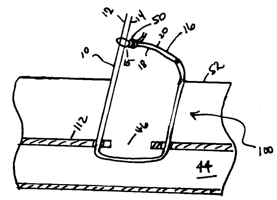
[0035]FIGS. 4A-4B illustrate the cinching loop used in combination with a sheath and hemostatic promoting material in accordance with an alternative embodiment of the present invention. A sheath 60, or any other device such as a pusher, may be used to push the knot 50 toward the blood vessel puncture site 46. The sheath 60 may also deliver a hemostasis promoting material 62 to the puncture site 46 to ensure that hemostasis occurs at the puncture site 46 and within the adjacent tissue tract. Thus, the sheath 60 may act both as a pusher and a hemostatic promoting material delivery device.

[0036]Alternatively, the cinching loop may be used to position the hemostatic promoting material at the blood vessel puncture site as illustrated in FIG. 4B. With the hemostatic promoting material 122 in position at the blood vessel puncture site 46, the tissue cinching loop 100 initially formed by joining thread 16 to thread 10 such that the first and second segments of the first thread pass through ...

example 2

[0037]FIGS. 5A and 5B illustrate the cinching loop used in combination with a pusher and hemostatic promoting material in accordance with an embodiment of the present invention. Referring to FIG. 5A, when the cinching loop 100 is positioned around the blood vessel puncture site 46, the first thread 10 may be received by a lumen 132 of a pusher 134. This allows the user to keep first thread 10 taught or tensioned around the blood vessel puncture site 46. FIG. 5B illustrates the cinching loop and pusher at the blood vessel puncture site. The pusher 134 may have a hemostatic promoting material 136 positioned around a portion of the lumen 132 at the distal end 142 of the pusher 134. The hemostatic promoting material 136 may be surrounded by a dissolvable capsule 138, such as a gelatin capsule. When the capsule 138 is exposed to blood or other fluids, the capsule will dissolve thereby releasing the hemostatic material 136. The hemostatic material may then absorb the fluids and expand to ...

example 3

[0041]FIGS. 6A-6E illustrate the cinching loop used in combination with a pressure plug in accordance with an embodiment of the present invention. The pressure plug is described in detail in United States published patent application no. 2007 / 0282373 filed Nov. 24 2004, entitled “Hemostatic Pressure Plug” by inventors Mark Ashby, Roy D. Bertolet, Andrew Cragg, and Tin Tran, which is incorporated by reference herein in its entirety. FIGS. 6A and 6B illustrate the pressure plug 200 having suture retrieval needles 202a and 202b. The suture retrieval needles 202a, 202b may be secured on the pressure plug 200 with any absorbable and / or sealing material as described above. The suture retrieval needles 202a, 202b may be made of any biocompatible, flexible, durable material that will allow the needles 202a, 202b to be in a collapsed position for delivery within a patient, retract and retain its shape when exposed within the blood vessel lumen, and be able to pierce the blood vessel wall. Th...


PUM


Abstract

A solution is provided to release a tissue cinching loop within a body having a first thread having a first end and a second end, and a second thread having a first half having a first tip, a second half having a second tip, a bottom half having a link, and a top half, wherein the first end is inserted through the link. A first knot is formed around the first thread with the top half thereby forming a loop where the diameter of the loop decreases as the knot is pushed into the body and the first thread is pulled out of the body and where the loop is released within the body when the first end is pulled out of the body.

Description

CROSS REFERENCE TO RELATED APPLICATIONS[0001]This application claims priority on Provisional Application Ser. No. 60 / 528,383, entitled, “Cinching Loop”, by inventors Mark Ashby, Roy D. Bertolet, Tin T. Tran and Andrew H. Cragg, filed on Dec. 9, 2003.FIELD OF THE INVENTION[0002]The present invention relates to cinching loops for use in interventional and surgical procedures. More particularly, the present invention relates to cinching loops for use in interventional and surgical procedures which may be used with pressure plugs, hemostatic pledgets, hemostatic knot pushers, and the like.BACKGROUND OF THE INVENTION[0003]Suturing tissue or organs is a tedious and delicate procedure. This is due principally to the use of one single strand of suture thread, the thinness of the suturing thread, as well as its tendency to twist about its length. In one type of suturing procedure, the thread is directed through a tissue and the free ends thereof are wrapped to define a half-hitch knot that f...

Claims


Application Information

Patent Timeline
Patent Type & Authority Patents(United States)
IPC IPC(8): A61B17/04
CPCA61B17/0057A61B17/0469D04G1/00A61B17/12013A61B2017/00004A61B2017/00623A61B2017/0065A61B2017/00659A61B2017/00663A61B2017/00893A61B2017/0472A61B2017/0475A61B2017/0477
Inventor ASHBY, MARKBERTOLET, ROY D.TRAN, TIN T.CRAGG, ANDREW H.
Owner SUB Q
Why Eureka
Try Eureka