Fusing device and image forming apparatus having the same

a technology of forming apparatus and fusing device, which is applied in the direction of electrographic process apparatus, instruments, optics, etc., can solve the problems of unfavorable fixation and inability to increase the pressing force in the nip area (n), so as to reduce the warm-up time and speed up printing

Active Publication Date: 2011-02-01
HEWLETT PACKARD DEV CO LP
View PDF8 Cites 37 Cited by
  • Summary
  • Abstract
  • Description
  • Claims
  • Application Information

AI Technical Summary

Benefits of technology

[0010]The present general inventive concept provides a fusing device capable of reducing a warm-up time and subsequently providing speedy printing.
[0011]The present general inventive concept also provides a fusing device capable of increasing an effective width of a nip area, increasing a pressure, and subsequently improving image fixing performance.

Problems solved by technology

Because the pressing force is limited in the nip areas (N), unsuccessful fixation may occur due to lack of pressing force.
However, the pressing force cannot be increased in the nip areas (N), because the heating member 60 can be damaged by the pressure and heat deformation.

Method used


Image

  • Fusing device and image forming apparatus having the same
  • Fusing device and image forming apparatus having the same
  • Fusing device and image forming apparatus having the same

Examples


Embodiment Construction

[0060]Reference will now be made in detail to the embodiments of the present general inventive concept, examples of which are illustrated in the accompanying drawings, wherein like reference numerals refer to the like elements throughout. The embodiments are described below in order to explain the present general inventive concept by referring to the figures.

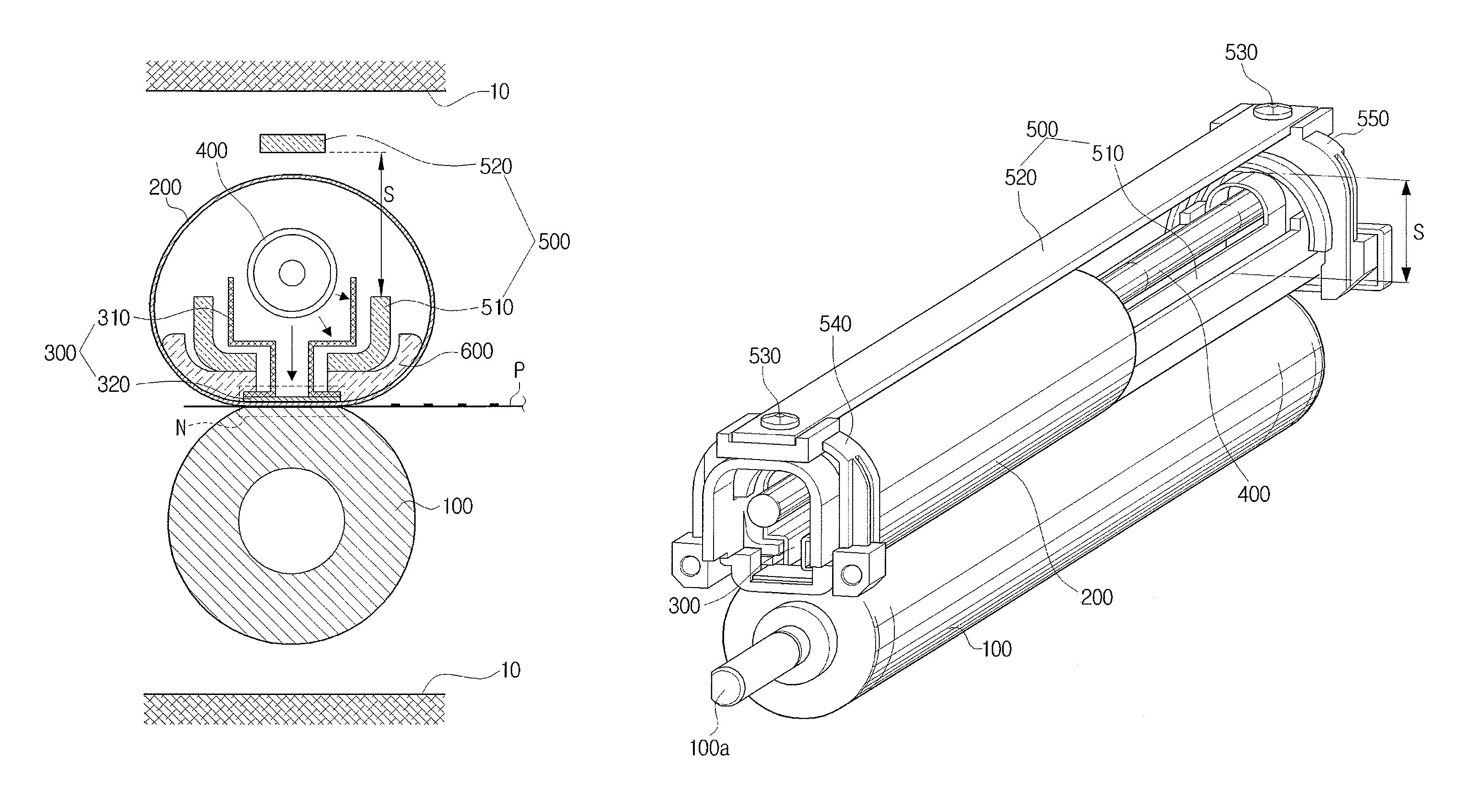
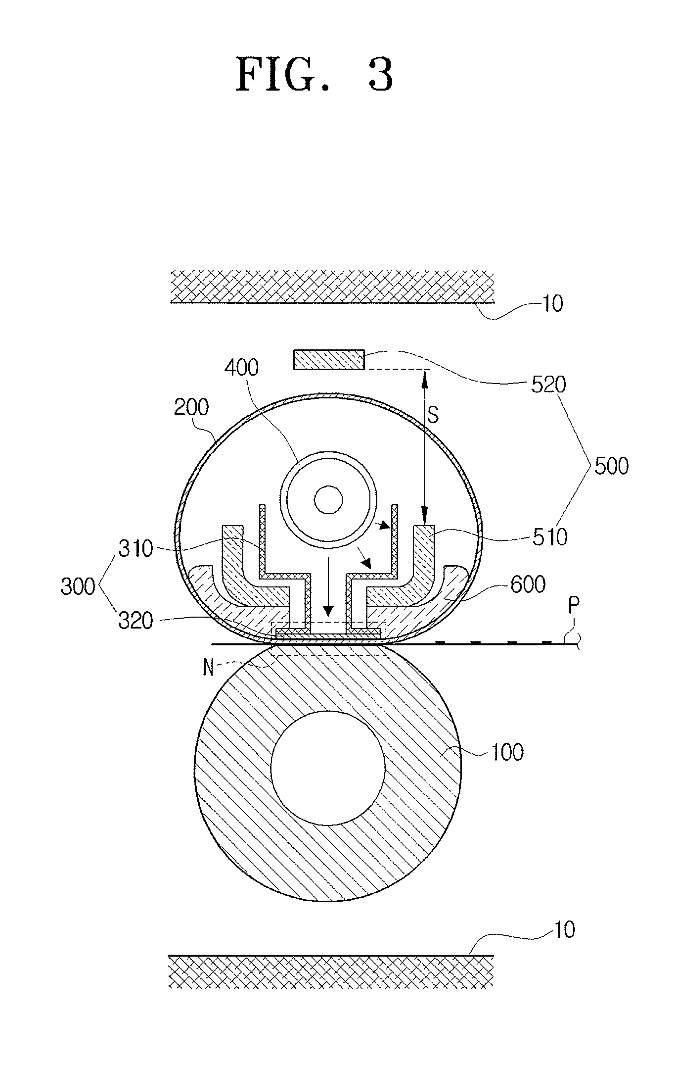
[0061]Referring to FIGS. 3 and 4, a fusing device according to an exemplary embodiment of the present general inventive concept includes a pressing unit 100, a belt unit 200 to rotate in contact with the pressing unit 100 at an outer surface thereof, a nip forming unit 300 in contact with an inner surface of the belt unit 200 to form a nip area (N) on a contact between the pressing unit 100 and the belt unit 200, a heating unit 400 to heat the nip forming unit 300 and the belt unit 200, and a support unit 500 to press the nip forming unit 300 toward the pressing unit 100 and having a space S through which the belt unit 200 is pa...


PUM


Abstract

A fusing device includes a rotatable pressing roller, a fusing belt to rotate by a rotational force transmitted from the rotatable pressing roller, a nip forming member to contact an inner surface of the fusing belt to form a nip on a contact area between the rotatable pressing roller and the fusing belt, a heating member formed in approximately an internal central portion of the fusing belt to heat the nip forming member and the fusing belt, an inner support member formed within the fusing belt to press a nip part of the nip forming member toward the rotatable pressing roller, and an outer support member formed outside the fusing belt, and both ends of the outer support member being engaged with the inner support member to thereby reinforce the strength of the inner support member and form a path for radiation heat to disperse. The support unit includes an inner support member placed within the belt unit, and an outer support member placed outside the belt unit, both ends of the outer support member being engaged with the inner support member to reinforce the strength of the inner support member and to form a path for a radiation heat to disperse.

Description

CROSS-REFERENCE TO RELATED APPLICATIONS[0001]This application claims priority under 35 U.S.C. §119(a) from Korean Patent Application No. 2007-99852, filed Oct. 4, 2007, in the Korean Intellectual Property Office, the entire disclosure of which is hereby incorporated in its entirety by reference.BACKGROUND OF THE INVENTION[0002]1. Field of the Invention[0003]The present general inventive concept relates to an image forming apparatus, and more particularly, to a belt type fusing device of an improved structure to fix a developer image onto a recording medium, and an image forming apparatus having the same.[0004]2. Description of the Related Art[0005]Electrophotographic image forming apparatuses, such as printers, copiers, or multi-function units, generally adopt a fusing device which fixes a developer image into a recording medium with heat and pressure. Among various fusing devices, roller and belt types of fusing devices are generally used.[0006]The main technical requirements of a ...

Claims


Application Information

Patent Timeline
Patent Type & Authority Patents(United States)
IPC IPC(8): G03G15/20
CPCG03G15/2064G03G2215/2035G03G15/2028G03G15/205G03G15/2053G03G15/2007
Inventor SHIN, SU-HOLEE, DONG-WOOKIM, TAE-GYUJUNG, CHANG-HOONKIM, TAE-HOONKIM, HWAN-HEE
Owner HEWLETT PACKARD DEV CO LP
Why Eureka
Try Eureka