Fixing device having an endless fixing belt and two-position disjunction mechanism

a fixing device and fixing belt technology, applied in the direction of instruments, electrographic process equipment, optics, etc., can solve the problems of defective fixing, inability to heat the fixing roller in a state where the fixing belt is not being rotated, and the respective abutting surfaces of the fixing roller and the fixing belt slip on each other, so as to reduce power consumption, shorten the warm-up time, and prolong the life

Active Publication Date: 2012-10-23
SHARP KK
View PDF14 Cites 24 Cited by
  • Summary
  • Abstract
  • Description
  • Claims
  • Application Information

AI Technical Summary

Benefits of technology

[0020]As described above, according to the fixing device of the present invention, the fixing belt satisfies 42.2≧ER≧0.1044×D×μ−0.5174. The fixing belt is thus driven by the fixing roller to rotate in the case where the fixing roller is driven by the first driving means to rotate in the state where the relative position is set to the second position.
[0021]This makes it possible not only to allow the fixing belt to have a longer life, but also to shorten the warm-up time and thus to reduce the power consumption.

Problems solved by technology

However, in the case where the fixing device using the belt fixing method has a fixing roller provided with an elastic layer having a large thickness and a low hardness, since the fixing roller cannot contain a heat source, it is impossible to heat the fixing roller in a state where the fixing belt is not being rotated.
This problematically leads to defective fixing.
However, in the case where the fixing belt of the conventional fixing device using the belt fixing method is driven to rotate, respective abutting surfaces of the fixing roller and the fixing belt slip on each other due to rigidity of the fixing belt.
This makes it difficult to appropriately rotate the fixing belt only by driving the fixing roller to rotate.
This method, however, has caused problems (1) and (2) below.
(1) Since the pressing roller is driven to rotate while being constantly pressed with great force against a surface of the fixing belt during a warm-up or when the image forming apparatus is ready on standby, the fixing belt is easily deteriorated, and thus has a shortened life.
Therefore, the above rotation under pressure affects the fixing belt significantly.
This excessively raises a temperature of the pressing roller.
Thus, even if the pressing roller is provided with a heat source and a temperature sensor so as to control the temperature of the pressing roller, it is still difficult to control the temperature so that the pressing roller has a predetermine temperature.

Method used


Image

  • Fixing device having an endless fixing belt and two-position disjunction mechanism
  • Fixing device having an endless fixing belt and two-position disjunction mechanism
  • Fixing device having an endless fixing belt and two-position disjunction mechanism

Examples


embodiment 1

[0037][Embodiment 1]

[0038]The following describes an embodiment of the present invention. The present embodiment describes a case in which the present invention is applied to a multifunction color printer.

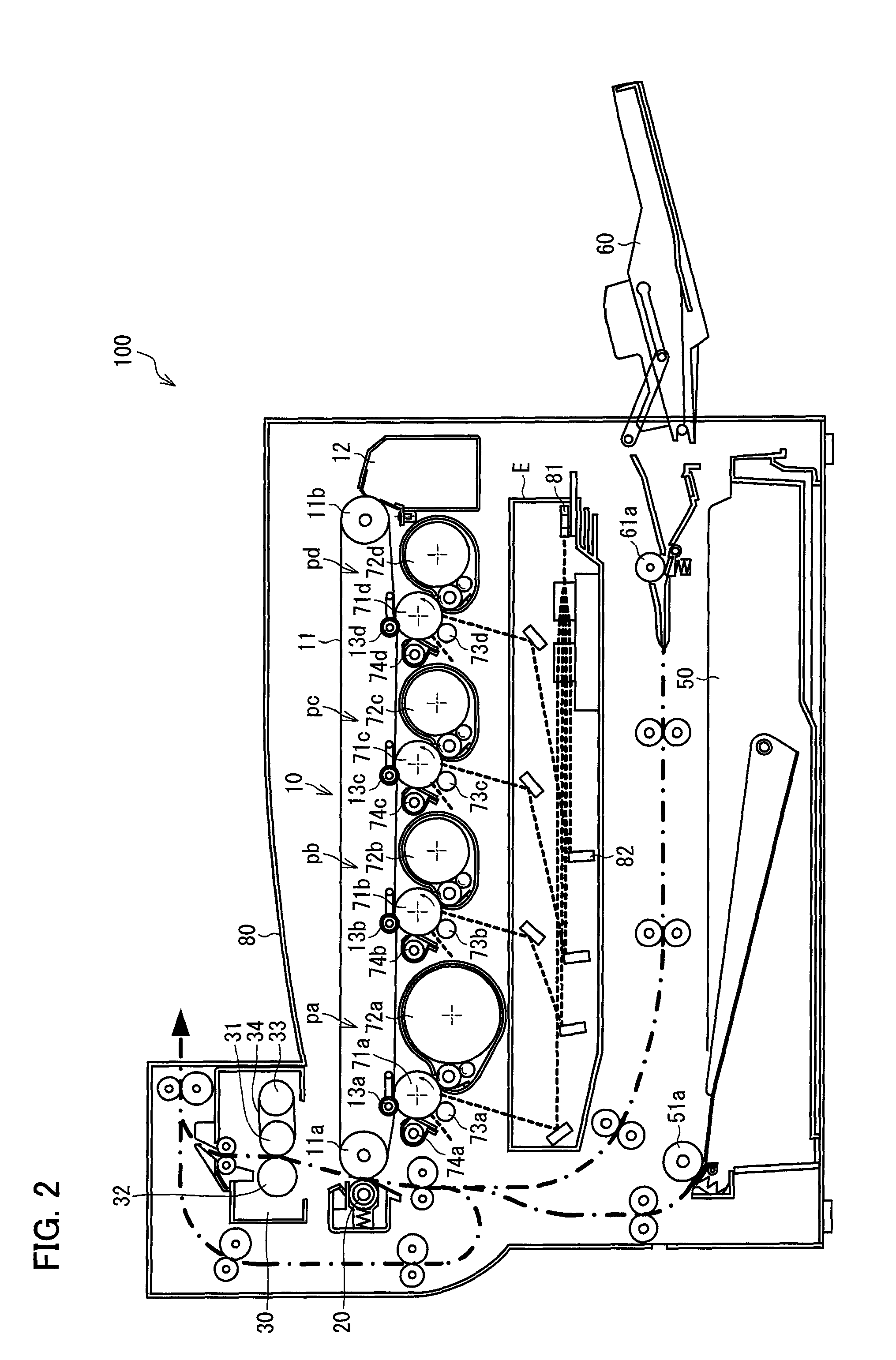
[0039]FIG. 2 is a cross-sectional view illustrating an image forming apparatus (multifunction color printer) 100 of the present embodiment. As illustrated in FIG. 2, the image forming apparatus 100 includes: an optical system (exposure) unit E; four sets of visible image forming units pa through pd; an intermediate transfer unit 10 including an intermediate transfer belt 11; a second transfer unit 20; a fixing unit (fixing device) 30; an internal paper feeding unit 50; and a manual paper feeding unit 60. Each member included in the image forming apparatus 100 is operated as controlled by a main control section (not shown) including components such as a CPU.

[0040]The visible image forming units pa through pd form toner images of black (K), cyan (C), magenta (M), and yellow (Y), resp...

embodiment 2

[0103][Embodiment 2]

[0104]Another embodiment of the present invention is described below. For convenience of explanation, members in the present embodiment that are functionally equivalent to their corresponding members described in Embodiment 1 are assigned the same reference numerals, and a description of such members is thus omitted.

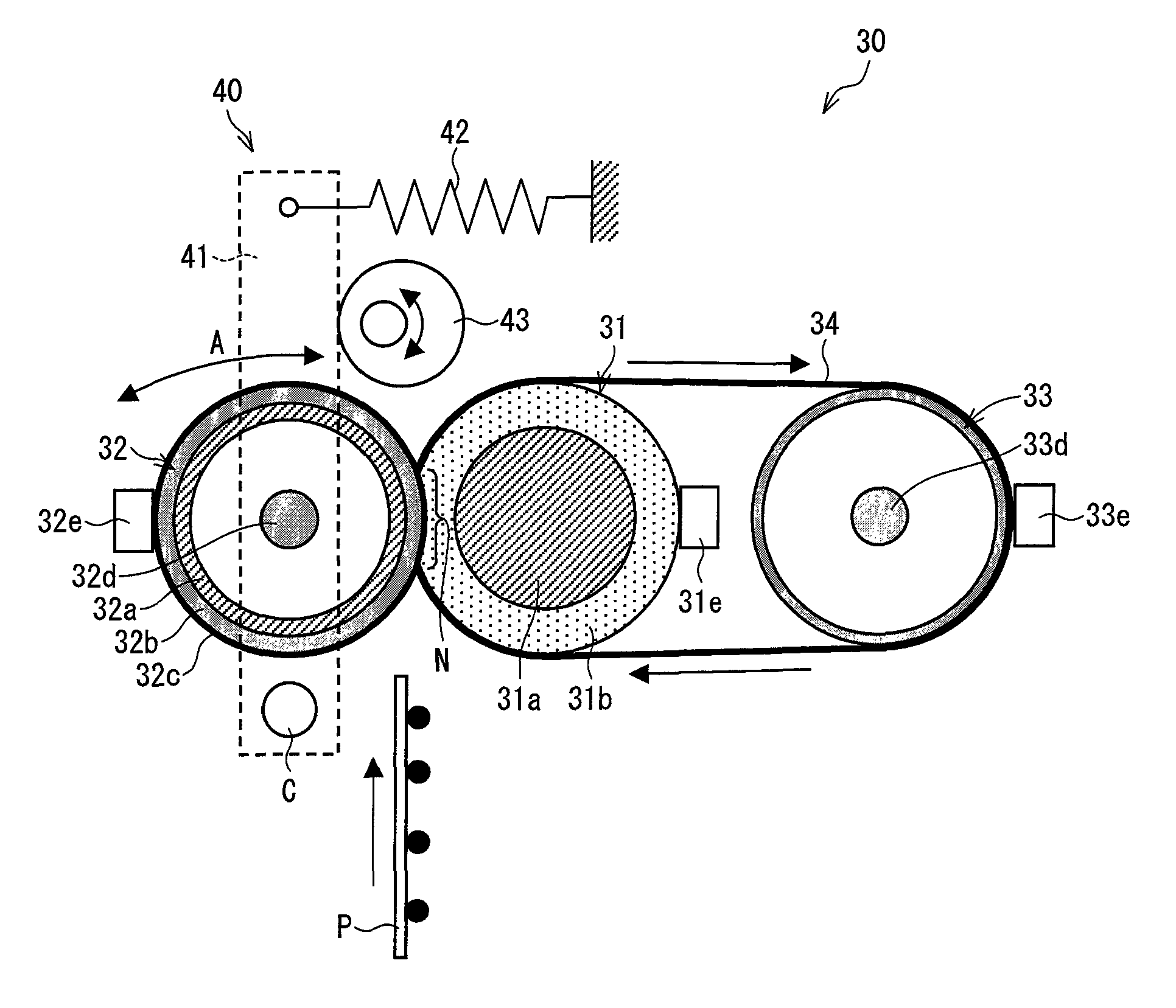
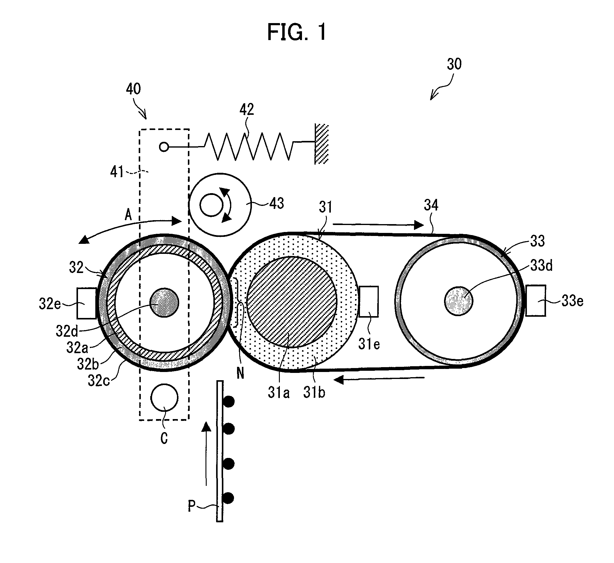
[0105]FIG. 11 is a cross-sectional view illustrating an arrangement of a fixing unit (fixing device) 130 according to the present embodiment. The fixing unit 130 is intended to replace the fixing unit 30 included in the image forming apparatus 100 described in Embodiment 1.

[0106]As illustrated in FIG. 11, the fixing unit 130 includes a plate-shaped heating member (belt holding member; first heating means) 133 to replace the heat roller 33 and the heater lamp 33d included in the fixing unit 30 of Embodiment 1. The plate-shaped heating member 133 serves to (i) support the fixing belt 34 so that the fixing belt 34 is rotatable and to (ii) heat the fixing...

embodiment 3

[0116][Embodiment 3]

[0117]Still another embodiment of the present invention is described below. For convenience of explanation, members in the present embodiment that are functionally equivalent to their corresponding members described in the above embodiments are assigned the same reference numerals, and a description of such members is thus omitted.

[0118]Embodiments 1 and 2 describe an arrangement in which the fixing unit includes a single belt member. The present embodiment, in contrast, describes an example arrangement in which the fixing unit includes a plurality of belt members.

[0119]FIG. 14 is a cross-sectional view illustrating a fixing unit (fixing device) 230 according to the present embodiment. As illustrated in FIG. 14, the fixing unit 230 includes: a fixing roller 31; a heat roller 33; a fixing pad 239a; a fixing belt 34; a pressing roller 32; a tension roller (second belt holding member) 238; a pressing pad 239b; a pressing belt 232; and an automatic pressure removing ...


PUM


Abstract

A fixing device having a fixing belt which satisfies 42.2≧ER≧0.1044×D×μ−0.5174, where: D represents an inner diameter of the fixing belt; A represents a second inner diameter of the fixing belt; ER represents an elongation rate of the fixing belt and is formulated as ER=(A−D) / D×100; and μ represents a coefficient of kinetic friction between the fixing belt and the fixing roller. The fixing device is thus arranged so that the fixing belt is driven by the fixing roller to rotate in a state where the pressing roller is separated from the fixing belt. This makes it possible to lengthen a life of a fixing belt, to shorten a warm-up time, and to reduce power consumption in a fixing device using a belt fixing method.

Description

[0001]This Nonprovisional application claims priority under 35 U.S.C. §119(a) on Patent Application No. 2009-102048 filed in Japan on Apr. 20, 2009, the entire contents of which are hereby incorporated by referenceTECHNICAL FIELD[0002]The present invention relates to a fixing device included in an electrophotographic image forming apparatus, and to an image forming apparatus including the fixing device.BACKGROUND ART[0003]In recent years, as a fixing device included in an electrophotographic image forming apparatus such as a copying machine and a printer, a fixing device using a belt fixing method has increasingly been used. In this method, a fixing belt is held around a fixing roller and a heat roller, and the fixing roller and a pressing roller are pressed against each other via the fixing belt (see Patent Literature 1).[0004]In the fixing device using the belt fixing method, the fixing belt having a heat capacity smaller than a heat capacity of the fixing roller is heated. Thus, ...

Claims


Application Information

Patent Timeline
Patent Type & Authority Patents(United States)
IPC IPC(8): G03G15/20
CPCG03G15/2035G03G2215/2009G03G2215/2025
Inventor KAGAWA, TOSHIAKI
Owner SHARP KK
Why Eureka
Try Eureka