Oil delivery system

a technology of oil delivery system and oil filter, which is applied in the direction of auxilary lubrication, machines/engines, mechanical equipment, etc., can solve the problems of increasing emissions, and achieve the effect of reducing engine warm-up time and reducing peak flow through the filter

Active Publication Date: 2012-06-07
FORD GLOBAL TECH LLC
View PDF5 Cites 23 Cited by
  • Summary
  • Abstract
  • Description
  • Claims
  • Application Information

AI Technical Summary

Benefits of technology

[0004]As such, one example approach to address the above issues is to separate a squirter passage from a feeder passage such that a cooler is positioned within the squirter passage and not included within the feeder passage. In this way, it is possible to lubricate various engine components, while reducing engine warm-up time. Specifically, the squirter passage includes a valve upstream from the cooler that selectively communicates the cooler with the feeder passage at a position upstream from a filter provided within the feeder passage. This configuration enables less-filtered oil to be routed through the squirter passage and provided to the cooler after engine warm up. Further, by taking advantage of only cooling less-filtered oil in one embodiment, a peak flow through the filter can be reduced. In an alternative, more-filtered and less-filtered oil may be selectively cooled, for example.

Problems solved by technology

Further, by not controlling oil flow to the piston squirters, engine warm up is delayed, which also increases emissions.

Method used


Image

  • Oil delivery system
  • Oil delivery system
  • Oil delivery system

Examples


Embodiment Construction

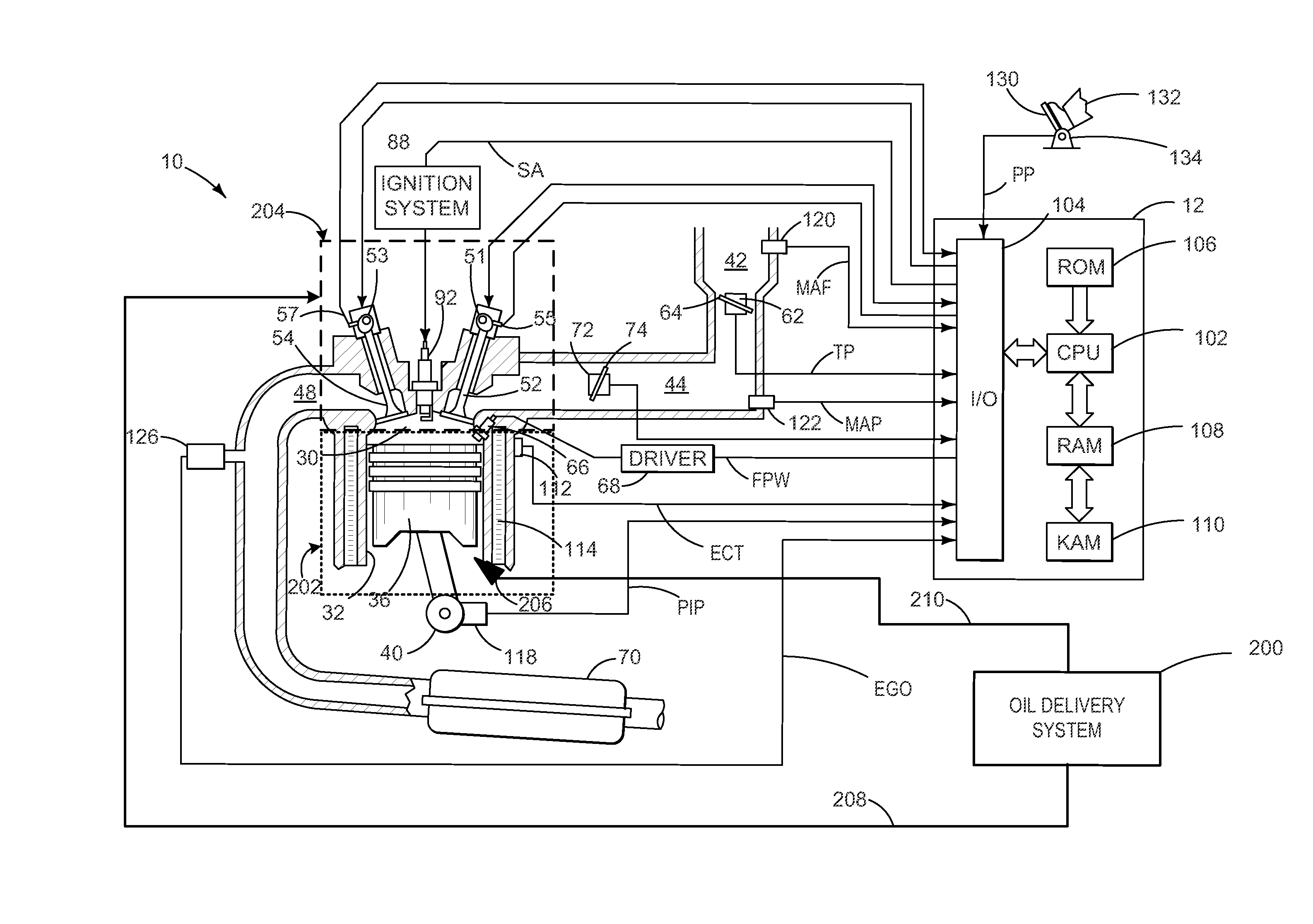
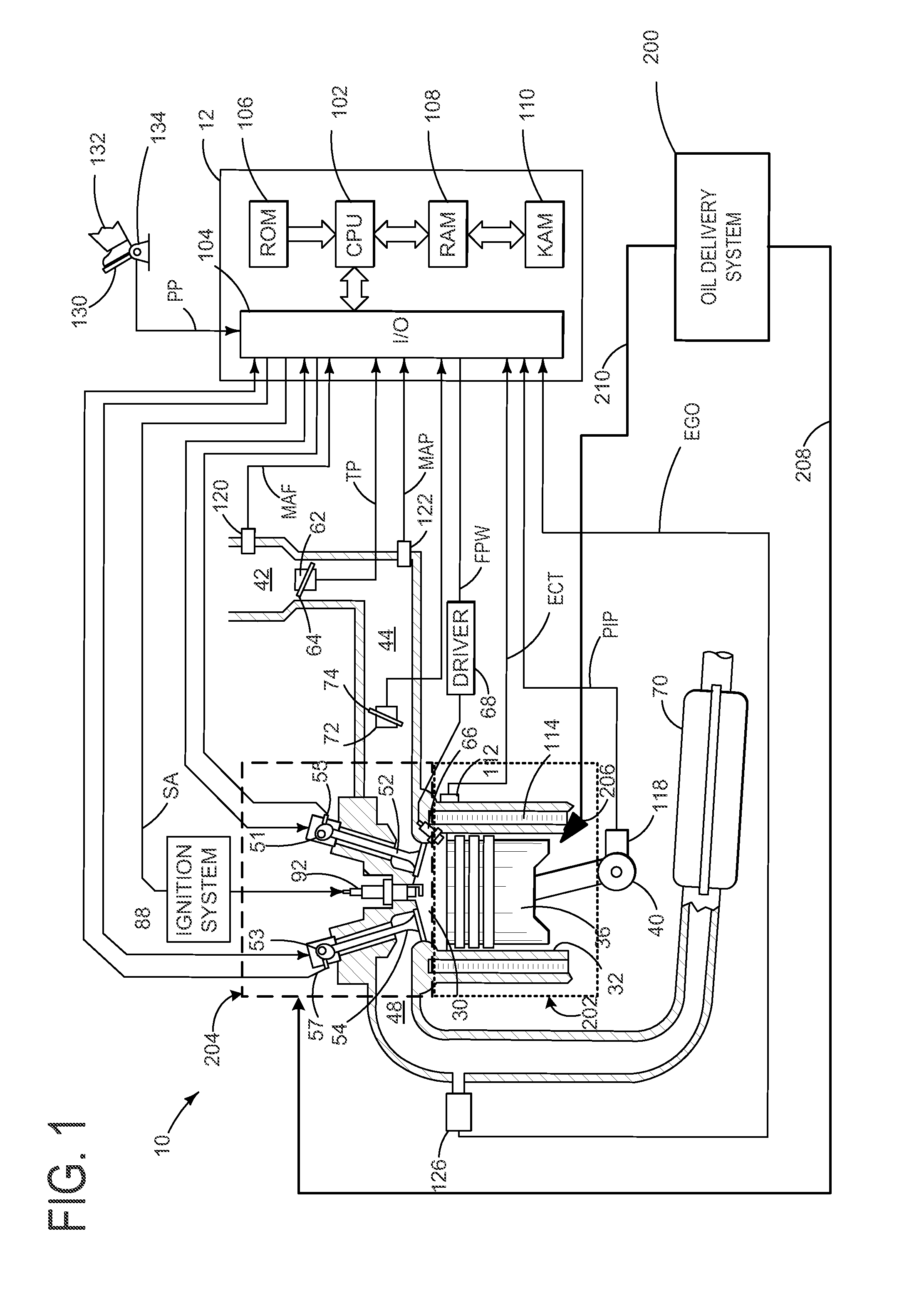
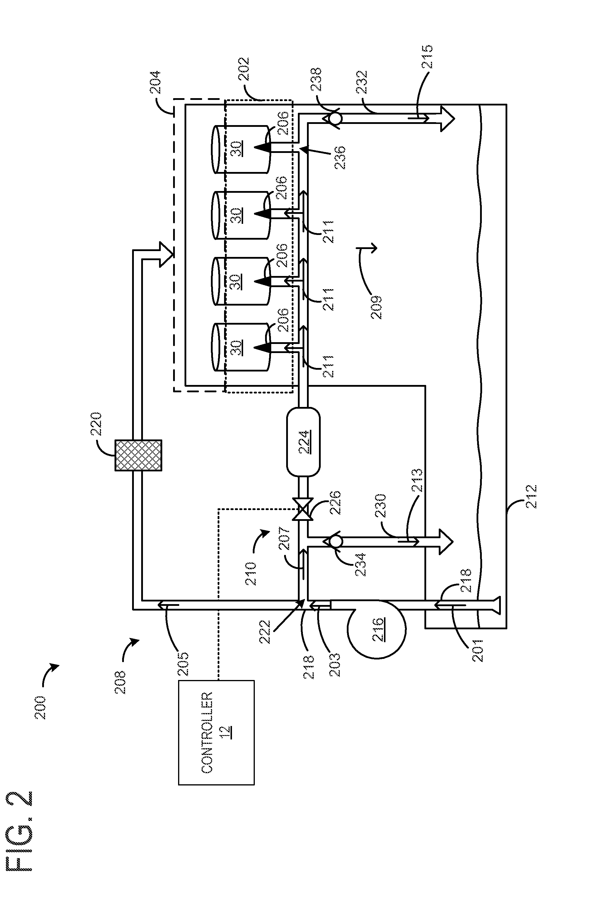
[0011]The following description relates to an oil delivery system that includes a filtering circuit and a cooling circuit, which are arranged in such a way that cooled oil is selectively provided to a plurality of piston squirters. This arrangement allows for rapid engine warm up as oil flow may be circulated through a cooler of the cooling circuit after engine warm up. Further, by separating the filtering circuit from the cooling circuit, various engine components can be lubricated during various operating conditions including engine warm up. Various valves may be included in the disclosed system to selectively communicate the cooling circuit with a feeder passage. For example, during engine warm up, unfiltered oil may be directed to the oil supply to bypass the cooler. Further, when the engine operating temperature exceeds a predetermined threshold, unfiltered oil may be permitted to flow through a cooler and to the downstream plurality of piston squirters. Additionally, the oil d...


PUM


Abstract

Systems and methods for delivering oil to an engine are provided herein. According to one embodiment, the oil delivery system includes an oil supply, a feeder passage fluidically coupled to the oil supply and a cylinder head, the feeder passage coupled to a pump and a filter positioned downstream from the pump. The oil delivery system further includes a squirter passage in fluidic communication with a plurality of piston squirters and the feeder passage at a position between the pump and the filter. In this way, less-filtered oil is selectively routed through a cooling circuit to reduce engine warm-up time.

Description

BACKGROUND AND SUMMARY[0001]Vehicles may use an oil delivery system to lubricate and / or cool various components of an internal combustion engine.[0002]For example, U.S. Pat. No. 7,823,545 describes a piston squirter system that squirts oil on an underside of each piston. The system includes a gallery that connects a pump to the piston squirters. Further, the system is arranged such that it excludes control valves, and oil is delivered to the piston squirters in response to oil pressure.[0003]The inventors herein have recognized various issues with the above system. In particular, by excluding control valves, cooled oil is circulated through the system at any engine operating condition. Further, by not controlling oil flow to the piston squirters, engine warm up is delayed, which also increases emissions.[0004]As such, one example approach to address the above issues is to separate a squirter passage from a feeder passage such that a cooler is positioned within the squirter passage a...

Claims


Application Information

Patent Timeline
Patent Type & Authority Applications(United States)
IPC IPC(8): F01M1/02
CPCF01M1/08F01M5/02F01M1/16
Inventor ULREY, JOSEPH NORMANMAKI, CLIFFWILLIAMS, RICK L.BARBER, EVA
Owner FORD GLOBAL TECH LLC
Why Eureka
Try Eureka