
Fixing device and image forming apparatus using the same

a technology of fixing device and image forming apparatus, which is applied in the direction of electrographic process apparatus, instruments, optics, etc., can solve the problems of increasing the temperature of the fixing roller, increasing the heating time of the fixing device, so as to reduce the warm-up time

Inactive Publication Date: 2008-05-06
RICOH KK
View PDF22 Cites 28 Cited by
  • Summary
  • Abstract
  • Description
  • Claims
  • Application Information

AI Technical Summary

Benefits of technology

[0010]It is an object of the present invention to provide a fixing device capable of reducing a warm-up time and obviating irregularity in temperature ascribable to the image history of the previous image forming step occurring on a fixing member as well as irregularity in temperature in the lengthwise direction ascribable to the continuous feed of sheets of a relatively small size.

Problems solved by technology

This brings about a problem that the temperature of the fixing roller becomes irregular along the image pattern after the toner image has been fixed on the sheet.
Image defects include, e.g., irregularities in gloss and fixation and granularity.
In any case, however, a fixing device generates a considerable amount of thermal energy which is likely to effect various units around the fixing device.

Method used


Image

  • Fixing device and image forming apparatus using the same
  • Fixing device and image forming apparatus using the same
  • Fixing device and image forming apparatus using the same

Examples


Embodiment Construction

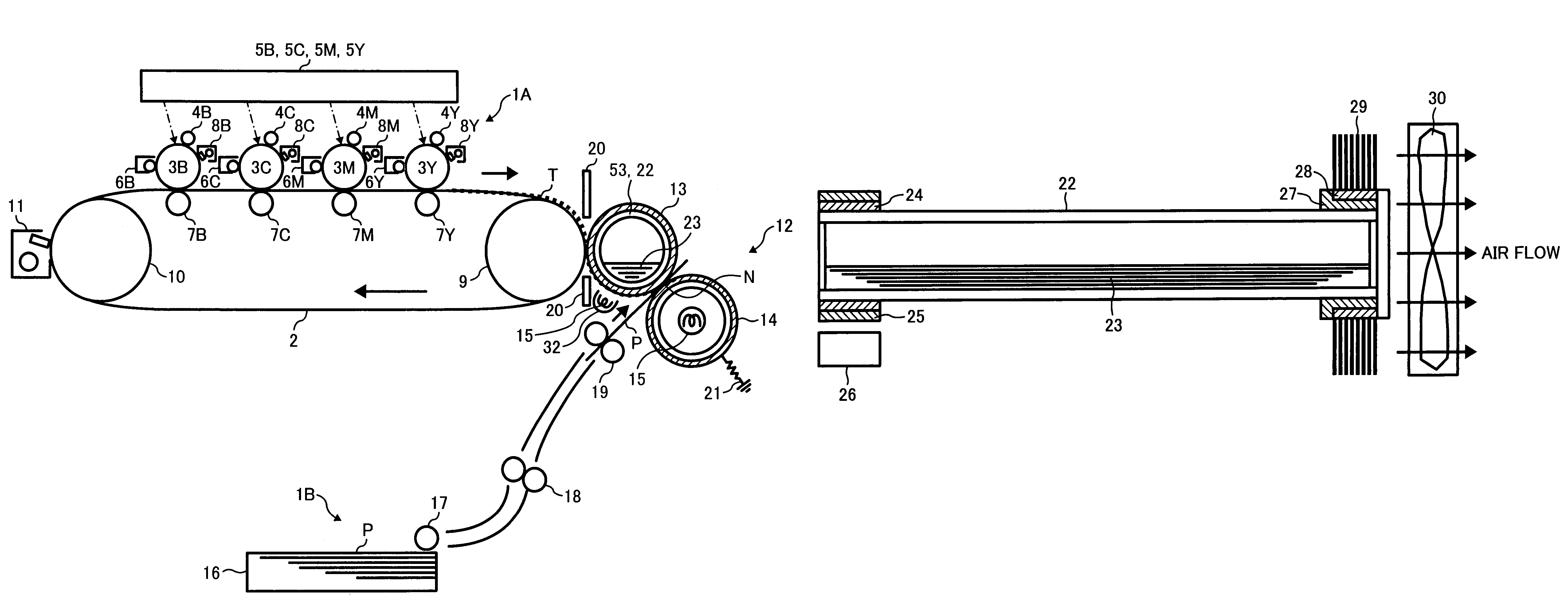
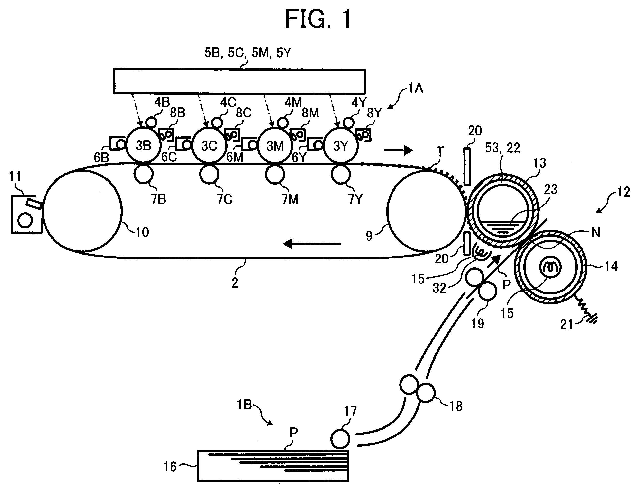
[0018]Referring to FIG. 1 of the drawings, an image forming apparatus to which the present invention is applied is shown and implemented as a tandem color copier by way of example. As shown, the color copier, generally 1, includes an image forming section 1A arranged at the center of the copier body, a sheet feeding section 1B positioned below the image forming section 1A and an image scanning section, not shown, positioned above the image forming section 1A.

[0019]The image forming section 1A includes an intermediate image transfer belt 2, which is a specific form of an intermediate image transfer body. An arrangement for forming images of colors complementary to separated colors is positioned on the upper run or image transfer surface of the intermediate image transfer belt (simply belt hereinafter) 2. More specifically, photoconductive elements or image carriers 3Y, 3M, 3C and 3B are arranged side by side along the image transfer surface of the belt 2 for carrying toner images of ...


PUM


Abstract

A fixing device for fixing image information on a recording medium passing a nip of the present invention includes a rotatable member for transferring and conveying a non-fixed image, a first heating means for heating an image present on the rotatable member and a rotatable pressing member forming a nip in combination with the rotatable member. A heat pipe extends in parallel to the axis of the rotatable member. A radiating member is positioned at one end of the heat pipe while a heating member is positioned at the other end of the heat pipe.

Description

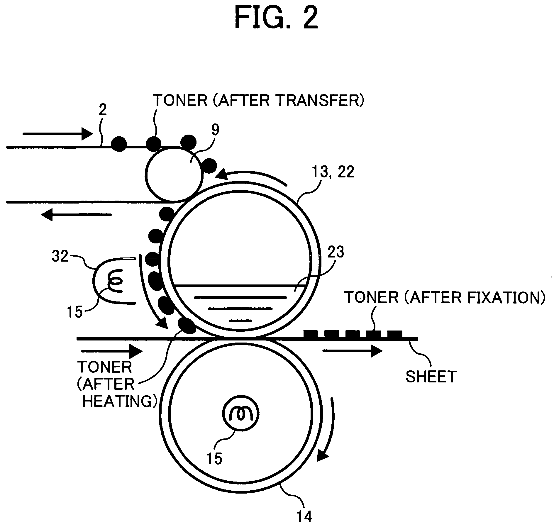
BACKGROUND OF THE INVENTION[0001]1. Field of the Invention[0002]The present invention relates to a fixing device for use in a copier, printer, facsimile apparatus or similar image forming apparatus and more particularly to a transfixing type of fixing device configured to melt with heat a toner image transferred to a fixing roller at a secondary image transferring position and then transfer and fix the toner image to a sheet or recording medium by tertiary image transfer.[0003]2. Description of the Background Art[0004]A transfixing type of fixing device directly heats a toner image transferred to a fixing roller with a radiation source and a reflector substantially surrounding the radiation source. In this type of fixing device, when a toner image is transferred to the fixing roller, toner is directly heated by radiant heat in part of the fixing roller where the toner image is present while the surface of the fixing roller is directly heated in the other part where the toner image i...

Claims


Application Information

Patent Timeline
Patent Type & Authority Patents(United States)
IPC IPC(8): G03G15/20
CPCG03G15/2053
Inventor ECHIGO, KATSUHIROFUJITA, TAKASHIKUROTAKA, SHIGEOKIKUCHI, HISASHISOMEYA, YUKIMICHIBABA, TOSHIHIKOKUNII, HIROYUKINAKAFUJI, ATSUSHIUE, KOHJI
Owner RICOH KK
Learn More