Handcuff apparatus

a technology of handcuffs and straps, which is applied in the direction of handcuffs, hose connections, transportation and packaging, etc., can solve the problems of unintentionally separated units, inability to grasp the free ends of two straps, and inability to intentionally separate them from each other, etc., to achieve maximum tensile strength, easy folding up, and easy unfolding

Inactive Publication Date: 2011-02-08
HARRINGTON ROBERT
View PDF21 Cites 17 Cited by
  • Summary
  • Abstract
  • Description
  • Claims
  • Application Information

AI Technical Summary

Benefits of technology

[0024]The first locking ratchet support member is flexible such that if an unlocking force is exerted on the first handcuff strap, the first locking ratchet support member presses the first unidirectional locking ratchets harder against an opposite wall of the first strap-reception channel, thereby increasing the locking power of the first unidirectional locking ratchets against the first strap-supported unidirectional ratchet members on the first handcuff strap.
[0048]Yet still another object of the present invention is to provide a new and improved handcuff apparatus including a locking head assembly having a movable locking member or clip movable between a first non-locking condition and a second locking condition to enhance the ability of the handcuff apparatus and of the locking head assembly thereof to resist picking.

Problems solved by technology

With a locking head that is a separate and distinct unit from the handcuffing straps, the two units can be unintentionally separated from each other, rendering both separated units useless.
Since the two straps are passed through the locking head in opposite directions, the two free ends of the two straps cannot be grasped by one hand of the person applying the handcuffs to the person to be restrained.
Such manipulation of the handcuff straps take time and effort.
Moreover, since the free ends of the handcuff straps are not connected together, once the handcuff straps are deployed on the person to be restrained, the two straps cannot be tightened together with a one-hand operation.
However, in none of the figures in U.S. Pat. No. 5,802,675 is there any disclosure of deploying both handcuff straps by a user employing only one hand.
For example, it would be desirable that the apparatus would be difficult to pick and unlock.

Method used


Image

  • Handcuff apparatus
  • Handcuff apparatus
  • Handcuff apparatus

Examples


Embodiment Construction

[0065]With reference to the drawings, a new and improved handcuff apparatus embodying the principles and concepts of the present invention will be described.

[0066]Turning to FIGS. 1-8, there is shown a preferred embodiment of the handcuff apparatus of the invention generally designated by reference numeral 10. In each of the figures, reference numerals are shown that correspond to like reference numerals that designate like elements shown in other figures.

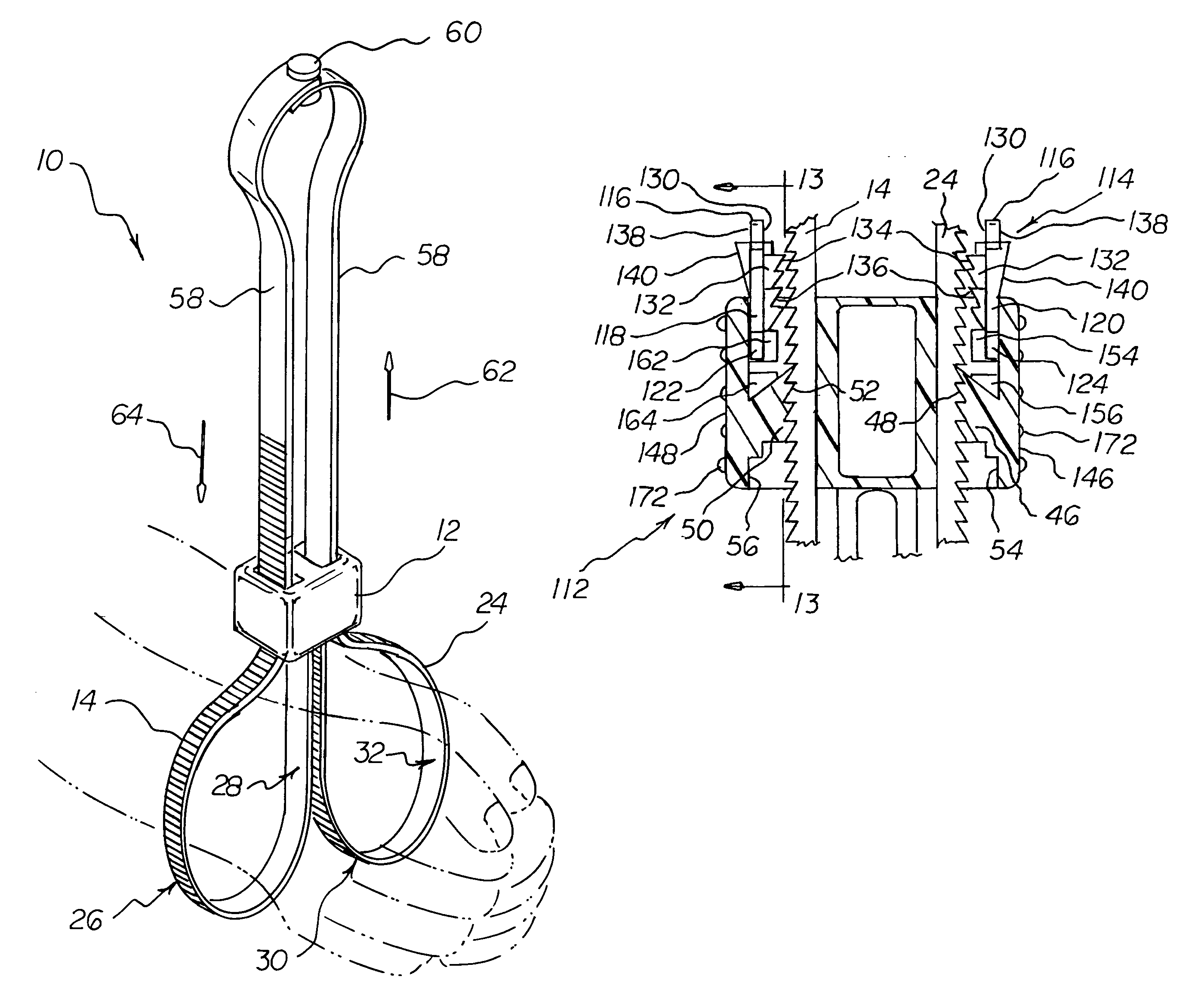
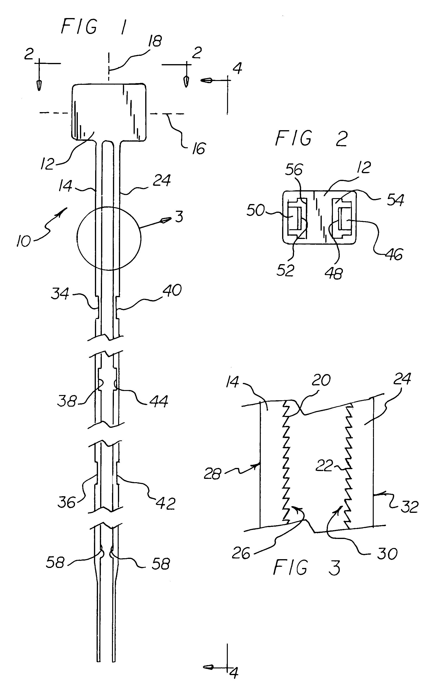
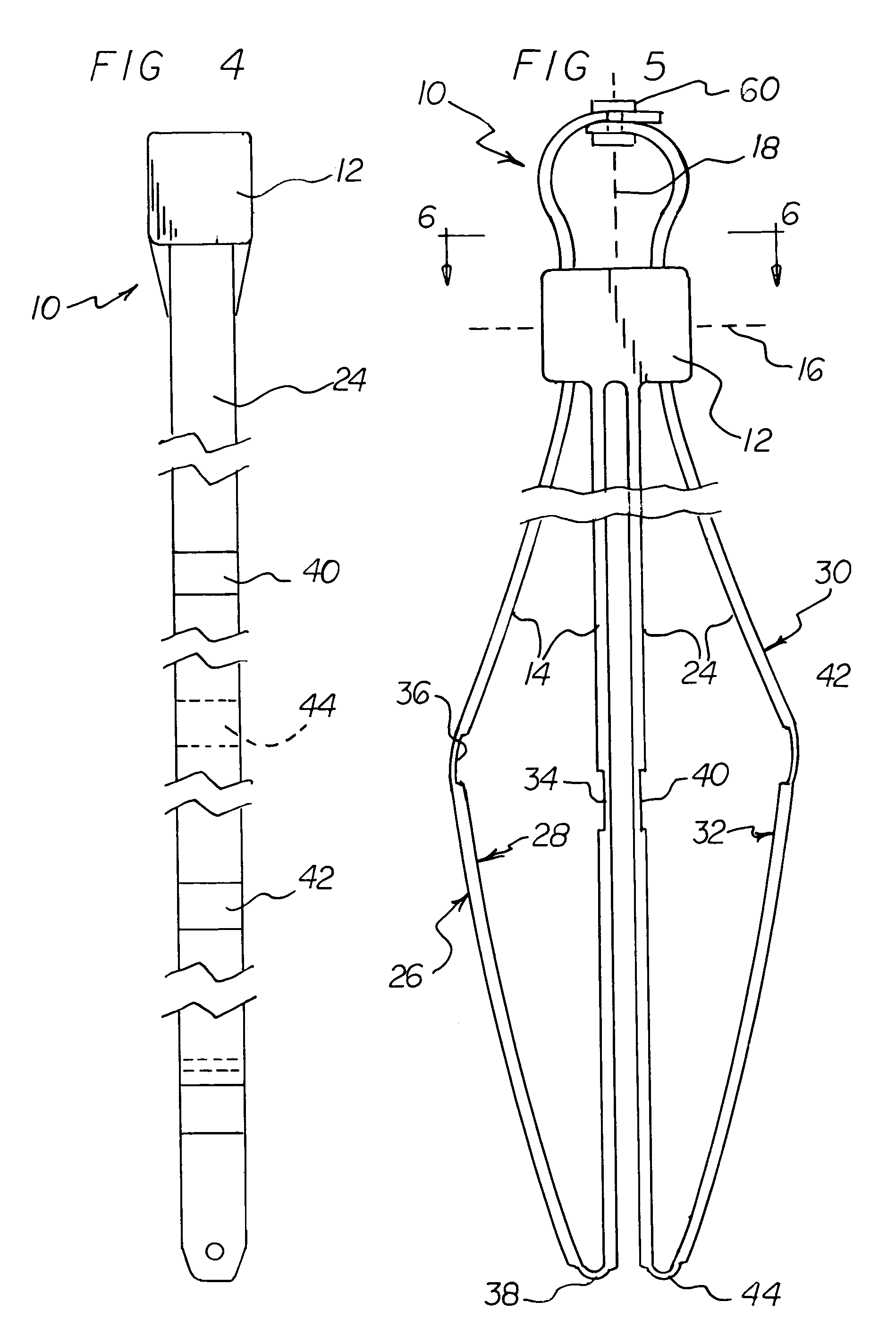
[0067]A handcuff apparatus 10 includes a combination locking head and strap support 12 which includes a first longitudinal axis 16. A first handcuff strap 14 and a second handcuff strap 24 are connected to the combination locking head and strap support 12. The first handcuff strap 14 and the second handcuff strap 24 are connected to the combination locking head and strap support 12 parallel to a second longitudinal axis 18 which is substantially perpendicular to the first longitudinal axis 16, wherein both the first handcuff strap ...


PUM


Abstract

A handcuff apparatus includes a combination locking head and strap support which includes a first longitudinal axis. A first handcuff strap and a second handcuff strap are connected to the combination locking head and strap support. Each of the respective first and second handcuff straps are connected to the combination locking head and strap support. Both of the handcuff straps extend outward from the combination locking head and strap support from the same side of the strap support. Each of the respective handcuff straps includes a ratchet-bearing side and a smooth side which contacts the skin of a person to be restrained. Respective strap-supported unidirectional ratchet members are located on the respective ratchet-bearing sides. The locking head and strap support is provided with a movable locking clip or member normally supported in a first or non-engagement position within a portion of the locking head.

Description

BACKGROUND OF THE INVENTION[0001]1. Field of the Invention[0002]The present invention relates generally to handcuff apparatuses, and, more particularly, to handcuff apparatuses that are especially adapted to be for single use and disposable.[0003]2. Description of the Prior Art[0004]Handcuff apparatuses are well known in the art. With one type of handcuff apparatus, a lock is provided in the apparatus, and a key is needed to unlock the lock. Such handcuff apparatuses can be used over and over again. With another type of handcuff apparatus, the apparatus is designed without having a key-operated lock. Such apparatuses are often for single use and are disposable.[0005]Throughout the years, a number of innovations have been developed relating to handcuff apparatuses that do not have key-controlled locks, and the following U.S. patents are representative of some of those innovations: U.S. Pat. Nos. 4,854,138, 5,088,158, 5,398,383, 5,443,155, 5,802,675, and Des. 347,156.[0006]More specif...

Claims


Application Information

Patent Timeline
Patent Type & Authority Patents(United States)
IPC IPC(8): E05B75/00
CPCE05B75/00Y10T24/1498Y10T24/141Y10T70/404
Inventor HARRINGTON, ROBERT
Owner HARRINGTON ROBERT
Why Eureka
Try Eureka