Image forming apparatus with multiple fixing unit attachment detection portions

a technology of image forming apparatus and fixing unit, which is applied in the direction of electrographic process apparatus, instruments, optics, etc., can solve the problems of failure to fix or in image formation, other parts of the fixing unit may not be inserted to their predetermined positions, and cannot be completely inserted to the end

Active Publication Date: 2011-02-08
CANON KK
View PDF19 Cites 3 Cited by
  • Summary
  • Abstract
  • Description
  • Claims
  • Application Information

AI Technical Summary

Benefits of technology

[0012]In view of the above-stated problems, it is an object of the present invention to provide an image forming apparatus capable of suppressing an attachment failure of a fixing unit.
[0013]It is another object of the present invention to provide an image forming apparatus capable of judging an attachment state of a fixing unit accurately.

Problems solved by technology

As the fixing unit is used repeatedly, a fixing roller may generate a flaw on the surface or a pressure roller may generate a wrinkle on the surface, and such a flaw or a wrinkle causes a failure in fixing or in image formation, and therefore a roller has to be replaced periodically.
The draw connectors used for this purpose typically have many connection terminals to feed electricity to a plurality of components, thus often requiring a force to detach and attach it.
However, even when the above-stated connectors are inserted to predetermined positions of the apparatus main body, other portions of the fixing unit may not be inserted to their predetermined positions.
Further, the above-stated drawer connectors that feed electricity to the fixing unit may not be inserted completely to the end physically even when the connector terminals between the fixing unit-side and the apparatus main body-side are electrically connected.
However, as described above, the drawer connectors that feed electricity to the fixing unit may not be inserted completely to the end physically even when the connector terminals between the fixing unit-side and the apparatus main body-side are electrically connected.
Therefore, the disclosed technique cannot completely prevent the case where a printing operation is permitted even when the fixing unit is aligned obliquely with reference to the correct direction of the image forming apparatus main body.
When the printing operation is performed while the fixing unit being aligned obliquely with reference to the correct direction of the image forming apparatus main body, there is a high possibility for a recording material to cause jam at the fixing unit portion.

Method used


Image

  • Image forming apparatus with multiple fixing unit attachment detection portions
  • Image forming apparatus with multiple fixing unit attachment detection portions
  • Image forming apparatus with multiple fixing unit attachment detection portions

Examples


Embodiment Construction

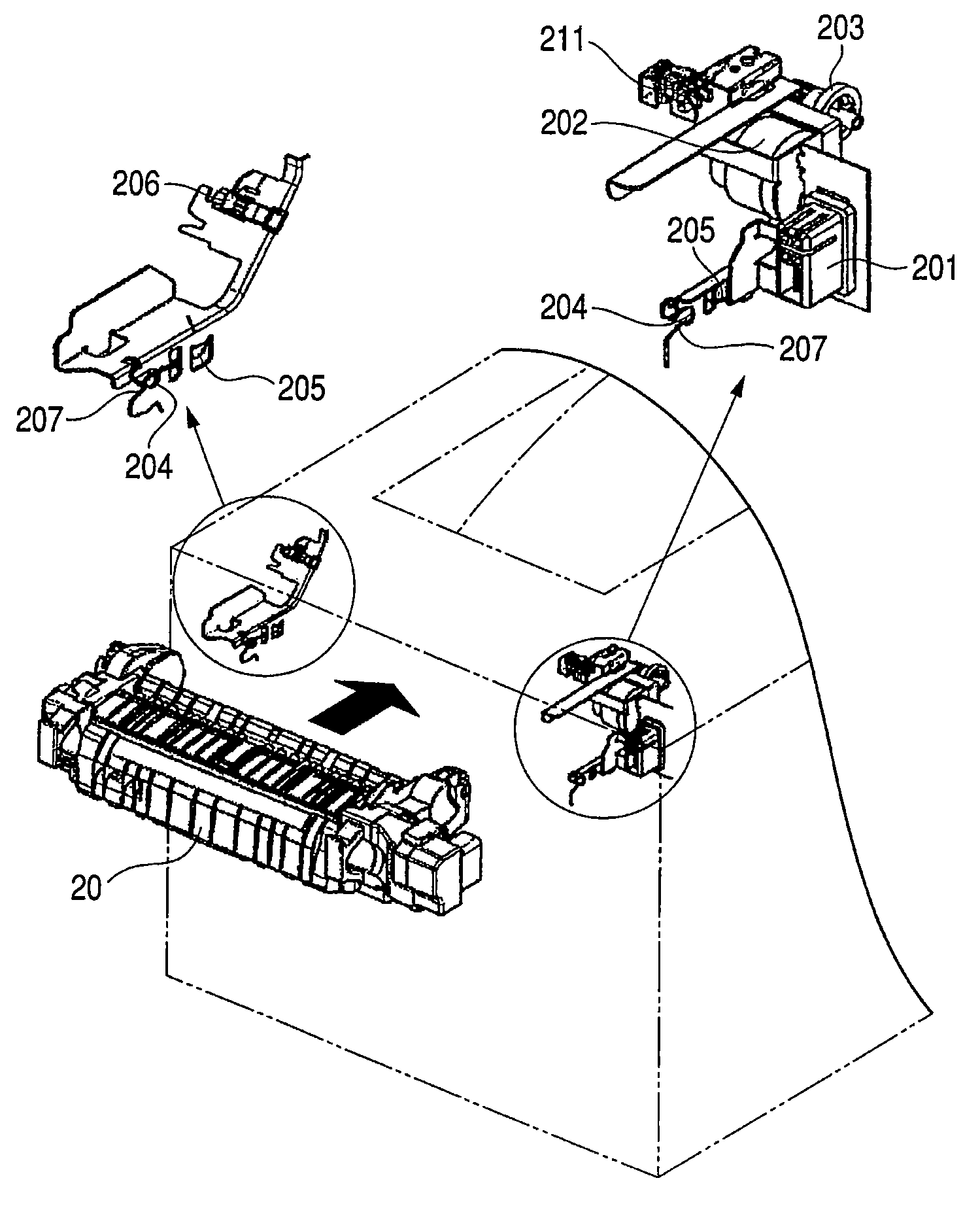
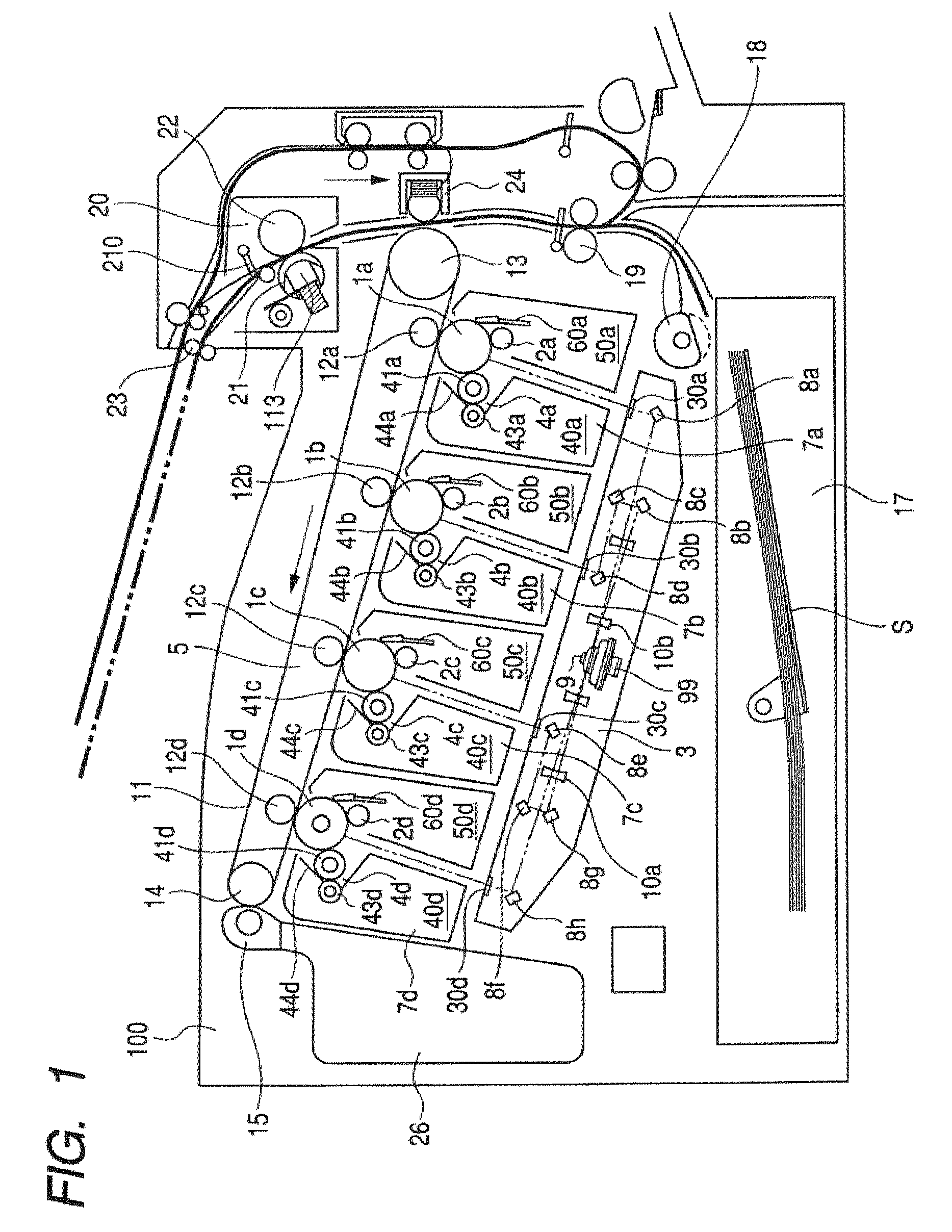
[0028]The following describes embodiments of the present invention in detail with reference to the drawings. FIG. 1 is a cross-sectional view illustrating the overall configuration of an electrophotographic full-color laser beam printer that is an image forming apparatus according to one embodiment of the present invention.

[0029]Overall Configuration of Image Forming Apparatus

[0030]In FIG. 1, an image forming apparatus 100 roughly includes an image formation portion, a feeding / transferring portion, a fixing portion, and a discharge portion. The image formation portion is provided at a center portion of the apparatus, the feeding / transferring portion is located from the lower right to the upper right of FIG. 1, and the fixing portion is located at the right uppermost of the same.

[0031](Image Forming Portion)

[0032]Firstly, the image forming portion will be described below. The image forming apparatus 100 includes four drum-shaped electrophotographic photosensitive members 1a to 1d (he...


PUM


Abstract

An image forming apparatus includes a main body and a fixing unit, as well as first and second fixing unit attachment detection portions, each of which includes an optical sensor. The fixing unit is detachably attached to the main body, and includes a unit-side connector which connects with a main body-side connector when the fixing unit is attached to the main body to receive power. The first fixing unit attachment detection portion is at a different position on the main body from where the main body-side connector is located in a longitudinal direction of the fixing unit. The second fixing unit attachment detection portion is at a different position on the main body from where the main body-side connector is located and a position where the first fixing unit attachment detection portion is disposed in the longitudinal direction of the fixing unit.

Description

BACKGROUND OF THE INVENTION[0001]1. Field of the Invention[0002]The present invention relates to an electrophotographic or an electrostatic-recording image forming apparatus, and more particularly relates to an image forming apparatus such as a copier, a laser beam printer, or a facsimile that are capable of forming a visual image on an image bearing member and transferring the visual image on a transfer material to obtain an image.[0003]2. Related Background Art[0004]Image forming apparatuses such as electrophotographic copier and printer are equipped with a fixing unit that heats a toner image formed on a recording material (transfer material) for fixing. As the fixing unit is used repeatedly, a fixing roller may generate a flaw on the surface or a pressure roller may generate a wrinkle on the surface, and such a flaw or a wrinkle causes a failure in fixing or in image formation, and therefore a roller has to be replaced periodically.[0005]Further, the fixing unit may have to be d...

Claims


Application Information

Patent Timeline
Patent Type & Authority Patents(United States)
IPC IPC(8): G03G15/20
CPCG03G21/1685G03G2221/1639G03G2221/1657
Inventor OBATA, SEIJI
Owner CANON KK
Why Eureka
Try Eureka