
X-ray source for a mobile X-ray diagnostic unit with a C-arm

a technology c-arm, which is applied in the field of x-ray diagnostic unit, can solve the problems of reducing the positioning ability reducing the mechanical stability and reducing the disadvantages of the x-ray diagnostic uni

Active Publication Date: 2011-02-15
ZIEHM IMAGING
View PDF32 Cites 9 Cited by
  • Summary
  • Abstract
  • Description
  • Claims
  • Application Information

AI Technical Summary

Problems solved by technology

Some X-ray diagnostic units suffer from disadvantages.
This could, in some cases, substantially reduce the positioning ability of the diagnostic unit.
Although the diameter of the C-arm may be increased to increase the opening width, this arrangement generally is not preferred for mobile equipment because of the corresponding increase in weight and decrease in mechanical stability due to the larger C-arm.
The disclosed asymmetrical arrangement of these diagnostic units is disadvantageous, because the lateral extent of the C-arm with the X-ray source is enlarged and the positioning ability is impaired, especially for under-the-table uses.
The high-voltage cable is not very flexible, particularly for voltages in the range of about 80 kV, and is difficult to accommodate given the constricted space conditions in the interior of a mobile X-ray diagnostic unit.

Method used


Image

  • X-ray source for a mobile X-ray diagnostic unit with a C-arm
  • X-ray source for a mobile X-ray diagnostic unit with a C-arm
  • X-ray source for a mobile X-ray diagnostic unit with a C-arm

Examples


Embodiment Construction

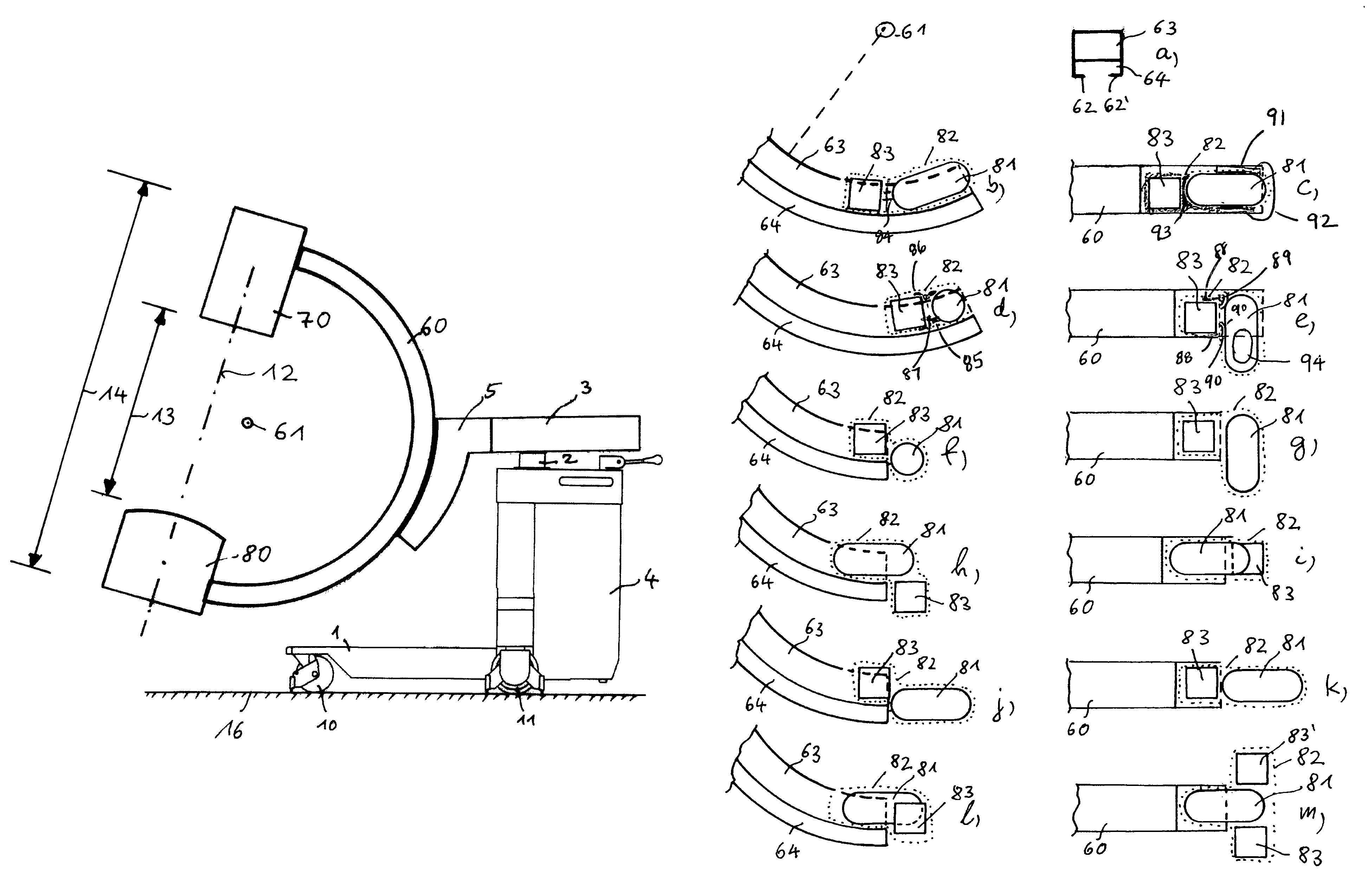
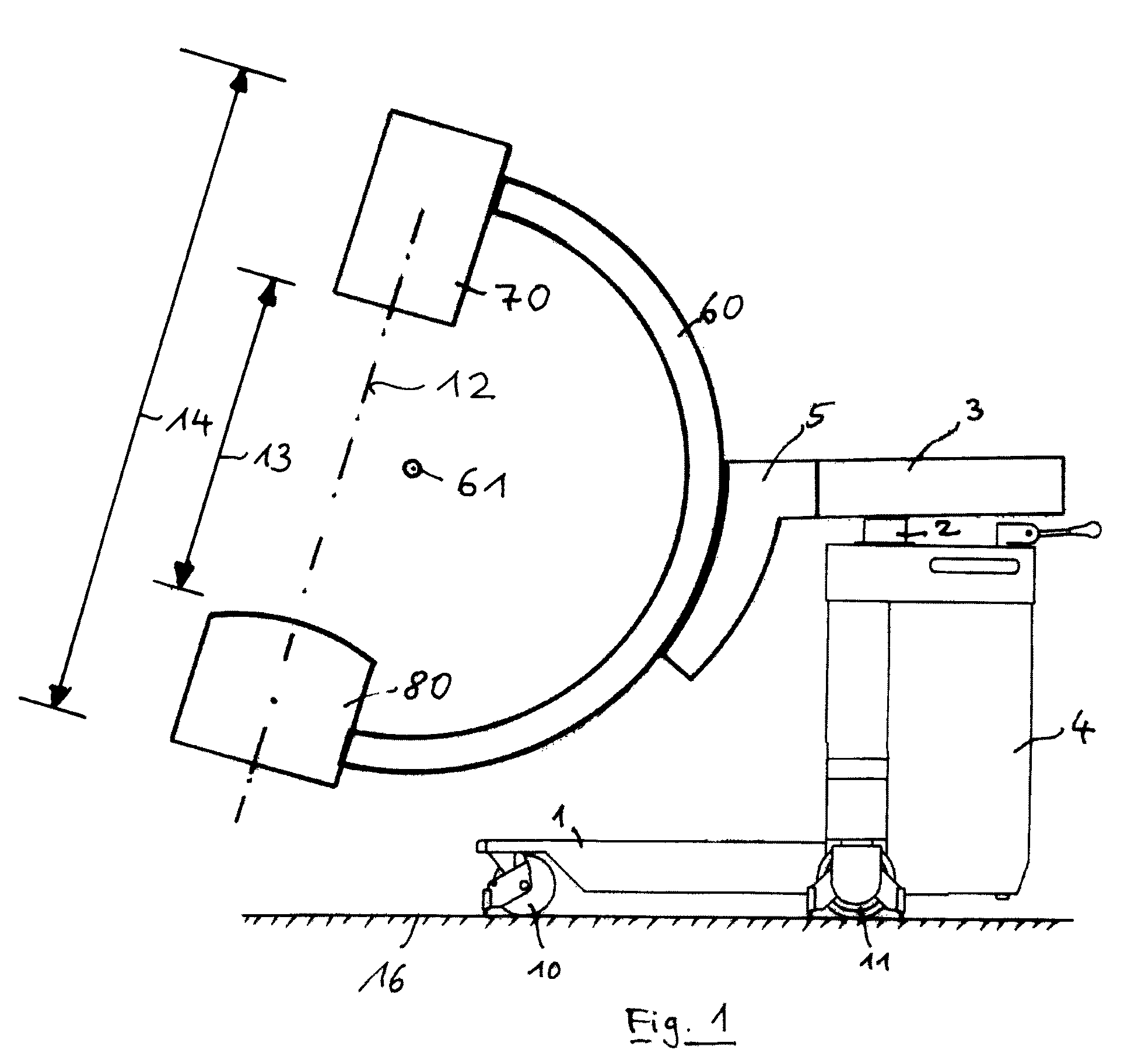
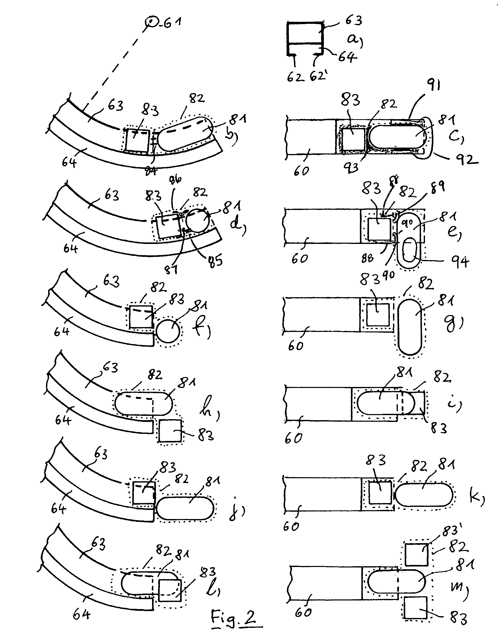
[0024]FIG. 1 schematically illustrates an embodiment of a mobile X-ray diagnostic unit having an arc-shaped C-arm 60. The illustrated embodiment of the C-arm 60 approximately forms a portion of a circle having a center point 61. The C-arm 60 is movably mounted along its periphery on a mount 5, which is connected to a horizontal guide 3 and a vertical column 2. The vertical column 2 is connected to a movable chassis 1, which includes an equipment cabinet 4. The movable chassis 1 has rollers 10, 11 that allow the X-ray diagnostic unit to be moved on the floor 16. The C-arm 60 may be adjusted vertically and horizontally by adjusting the column 2 and the guide 3, respectively. The C-arm 60 may be adjusted orbitally by circumferentially moving the C-arm 60 relative to the mount 5.

[0025]In some embodiments of the C-arm 60, an X-ray source 80 is positioned at one end of the C-arm 60, and an X-ray receiver 70 is positioned at the opposite end. X-rays may propagate from the X-ray source 80 t...


PUM


Abstract

Embodiments of an X-ray source for a mobile X-ray diagnostic unit with a C-arm include a generator vessel that may be mounted to a hollow frame of the C-arm. The generator vessel may have a first subregion with a high-voltage generator and a second subregion with an X-ray source. In some embodiments, the first subregion, the second subregion, or both subregions may be at least partially inside a portion of the hollow frame of the C-arm. The generator vessel may be at least partially filled with insulating oil for cooling the high-voltage generator and / or the X-ray source.

Description

CROSS-REFERENCE TO RELATED APPLICATIONS[0001]This application claims the right of priority under 35 U.S.C. §119(a)-(d) to German Patent Application No. DE 10 2007 026 677.6, filed Jun. 8, 2007, the entire disclosure of which is hereby incorporated by reference herein and made part of this specification.BACKGROUND[0002]1. Field[0003]The disclosure relates generally to X-ray diagnostic units and more particularly to an X-ray source for a mobile X-ray diagnostic unit with a C-arm.[0004]2. Description of the Related Art[0005]Various types of mobile X-ray diagnostic units are known. For example, German Patent No. DE 44 23 359 owned by the assignee of the present application describes an X-ray diagnostic unit with a C-arm that can be adjusted in multiple ways. An X-ray source and an X-ray receiver are arranged at opposite ends of the C-arm. In some embodiments of this unit, some or all of the adjustment axes are equipped with incremental encoders. Such an X-ray diagnostic unit advantageou...

Claims


Application Information

Patent Timeline
Patent Type & Authority Patents(United States)
IPC IPC(8): H05G1/10H05G1/06H05G1/02H01J35/02
CPCA61B6/4441A61B6/4488H05G1/06H05G1/10
Inventor DEHLER, JUERGENGUENTHER, MICHAELHOERNDLER, KLAUS
Owner ZIEHM IMAGING
Learn More