Polygonal radiation module having radiating members without light guiding board

a radiation module and radiating member technology, applied in the direction of lighting support devices, lighting and heating apparatus, instruments, etc., can solve the problems of weak illumination of the center of the light guiding board, unfavorable reduction of the thickness of the integral lcd, and increase the cost of producing the backlight modul

Active Publication Date: 2011-02-22
SOUTHERN TAIWAN UNIVERSITY OF TECHNOLOGY
View PDF7 Cites 51 Cited by
  • Summary
  • Abstract
  • Description
  • Claims
  • Application Information

AI Technical Summary

Benefits of technology

[0009]It is an object of the present invention to provide a polygonal radiation module having radiating me

Problems solved by technology

However, the conventional light guiding board of the backlight module is unfavorable for decreasing the thickness of the integral LCD.
Additionally, the installation of the light guiding board adversely increases the manufacturing procedure, which consequently raises the cost of producing the backlight module.2. The light sources of the backlight module are respectively disposed at the two sides of the light guiding board.
As a result, the illumination would perform well at the two sides of the light guiding board; however, the c

Method used


Image

  • Polygonal radiation module having radiating members without light guiding board
  • Polygonal radiation module having radiating members without light guiding board
  • Polygonal radiation module having radiating members without light guiding board

Examples


Embodiment Construction

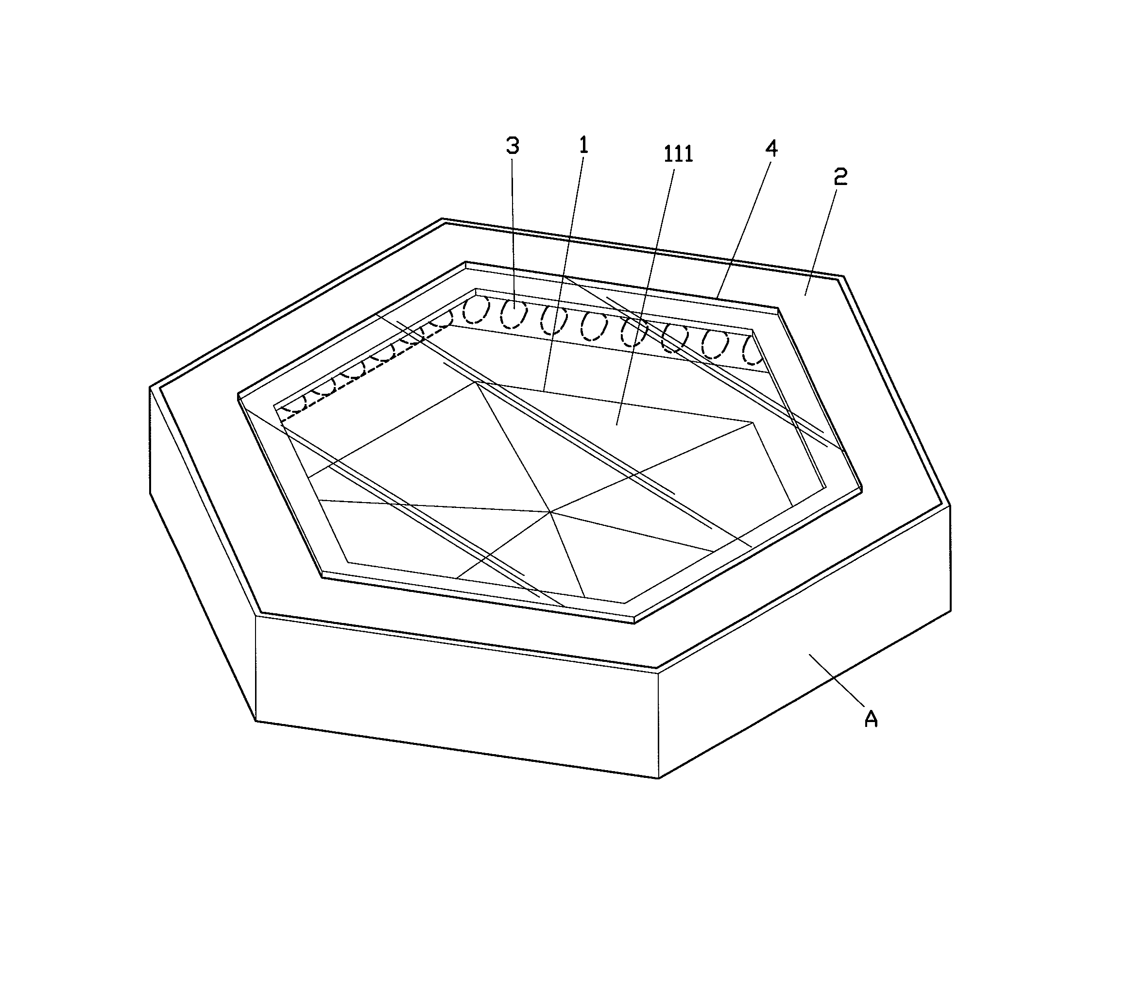
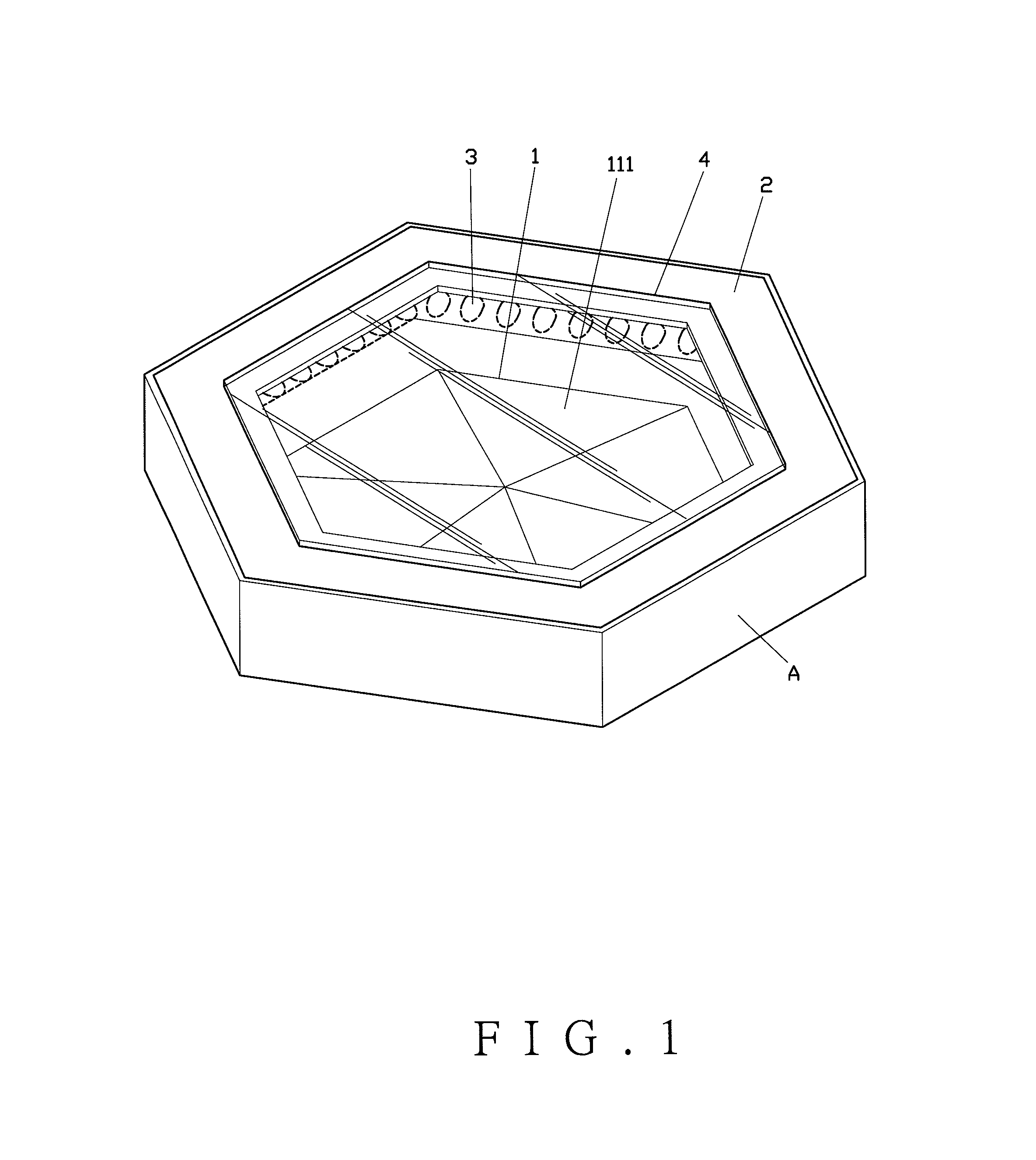
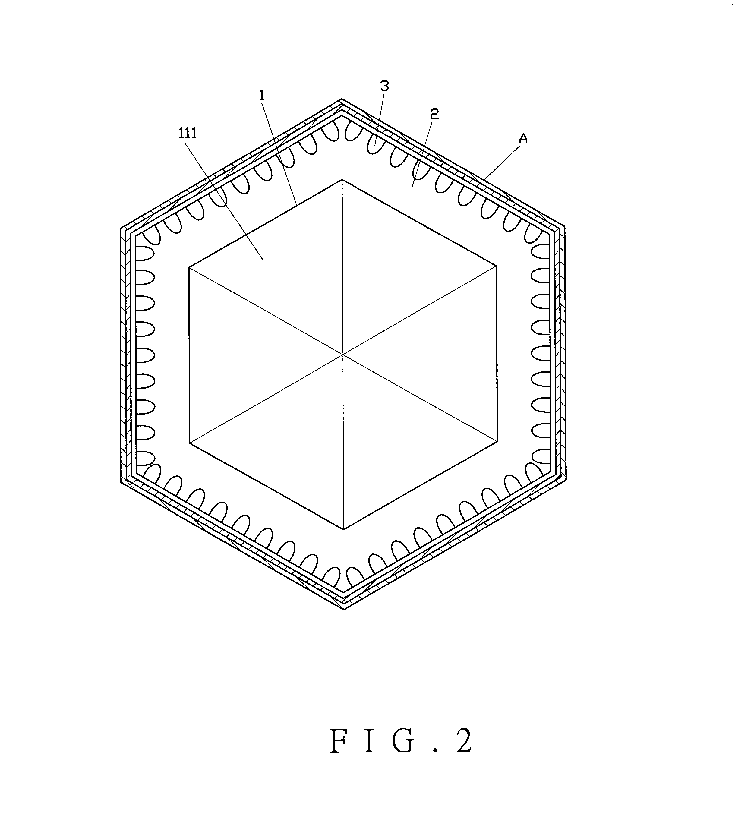
[0031]Referring to FIGS. 1 to 3, a polygonal radiation module having radiating members without a light guiding board according to a preferred embodiment of the present invention is mounted on a frame (A). The present invention comprises an optical plate (1), a reflecting housing (2), a plurality of radiating members (3), and a diffusion plate (4).

[0032]The optical plate (1) is formed by a polygon. In this embodiment, the polygon is formed by a hexagon. Wherein, the optical plate (1) includes at least one rising area (11) defined at a center thereof. The rising area (11) is formed by a rising surface (111). The reflecting housing (2) is connected to a periphery of the optical plate (1). The plurality of radiating members (3) adopting LED tubes surround the periphery of the optical plate (1) and fixed in the reflecting housing (2). Wherein, radiant half-intensity angles of the radiating members (3) are defined below 15 degrees with a high directivity. As it should be, when the radiant...


PUM


Abstract

A polygonal radiation module having radiating members without a light guiding board for a backlight module or a lighting device includes a polygonal optical plate with a rising area having a rising surface defined at a center thereof, a plurality of radiating members, and a diffusion plate. The radiating members surrounding a periphery of the optical plate possess radiant half-intensity angles of the radiation below 15 degrees for respectively forming optic axial directions thereof. Whereby, the optic axial directions of the radiating members face to the rising surface, and radiation fields are individually generated as pivoted by the optic axial directions to cast at the rising surface. Thus, an even radiating surface caused by a diffusion of light source from the diffusion plate could be preferably obtained even if no light guiding board is applied.

Description

BACKGROUND OF THE INVENTION[0001]1. Field of the Invention[0002]The present invention relates to a polygonal radiation module having radiating members without a light guiding board, especially to a radiating surface applied to a backlight module or other like emitting structure that does not require the light guiding board to achieve an even emission from a diffusion plate.[0003]2. Description of the Related Art[0004]Generally, in order to guide light for achieving an appropriate and multi-angled reflection, the backlight module would be commonly installed with a light guiding board. “A side-edged backlight module” disclosed in R.O.C. patent No. M359718 includes a plurality of LEDs, a light guiding board, a bright enhancement film, and a diffusion plate. Wherein, each LED has a radiating surface, and the radiating surfaces of the LEDs face to the same direction. The light guiding board disposed at one side of the LEDs has an incident plane, an emission plane, and a bottom. Wherein, ...

Claims


Application Information

Patent Timeline
IPC IPC(8): F21V33/00
CPCG02F1/133603G02F1/133605F21K9/68G02F1/133615Y10S362/80F21Y2115/10
Inventor KANG, CHIH-CHIEHLIN, JENG-FENGSYU, YA-RU
Owner SOUTHERN TAIWAN UNIVERSITY OF TECHNOLOGY
Why Eureka
Try Eureka