Radiation image capturing system
a radiation image and capturing system technology, applied in the field of radiation image capturing system, can solve the problems of low efficiency of the process of capturing the x-ray image receiver is not properly positioned in head-on alignment with the radiation source, and the inability of the x-ray image receiver to capture a radiation image of the affected part of the subject, etc., to achieve efficient and reliable placement and efficiently capture a radiation image of the subject
- Summary
- Abstract
- Description
- Claims
- Application Information
AI Technical Summary
Benefits of technology
Problems solved by technology
Method used
Image
Examples
first embodiment
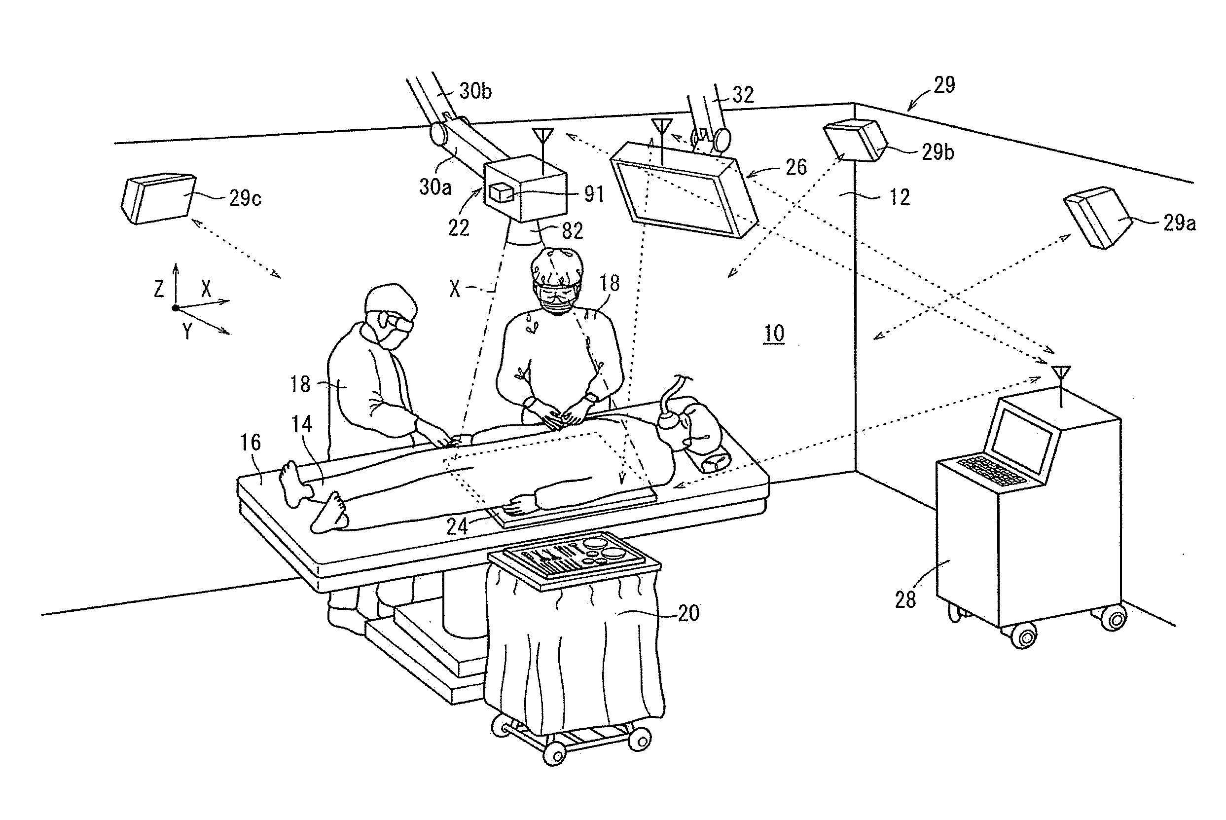
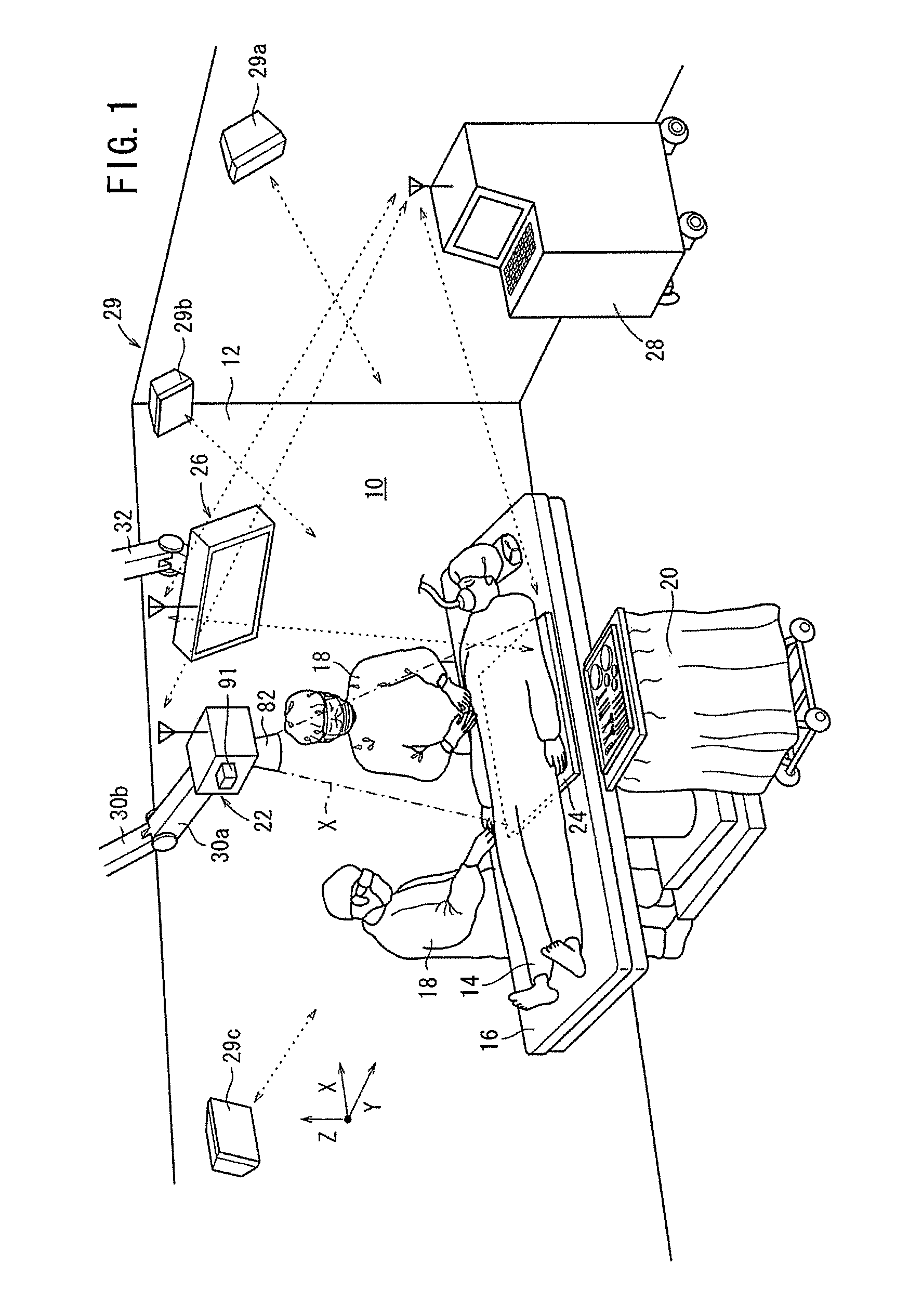
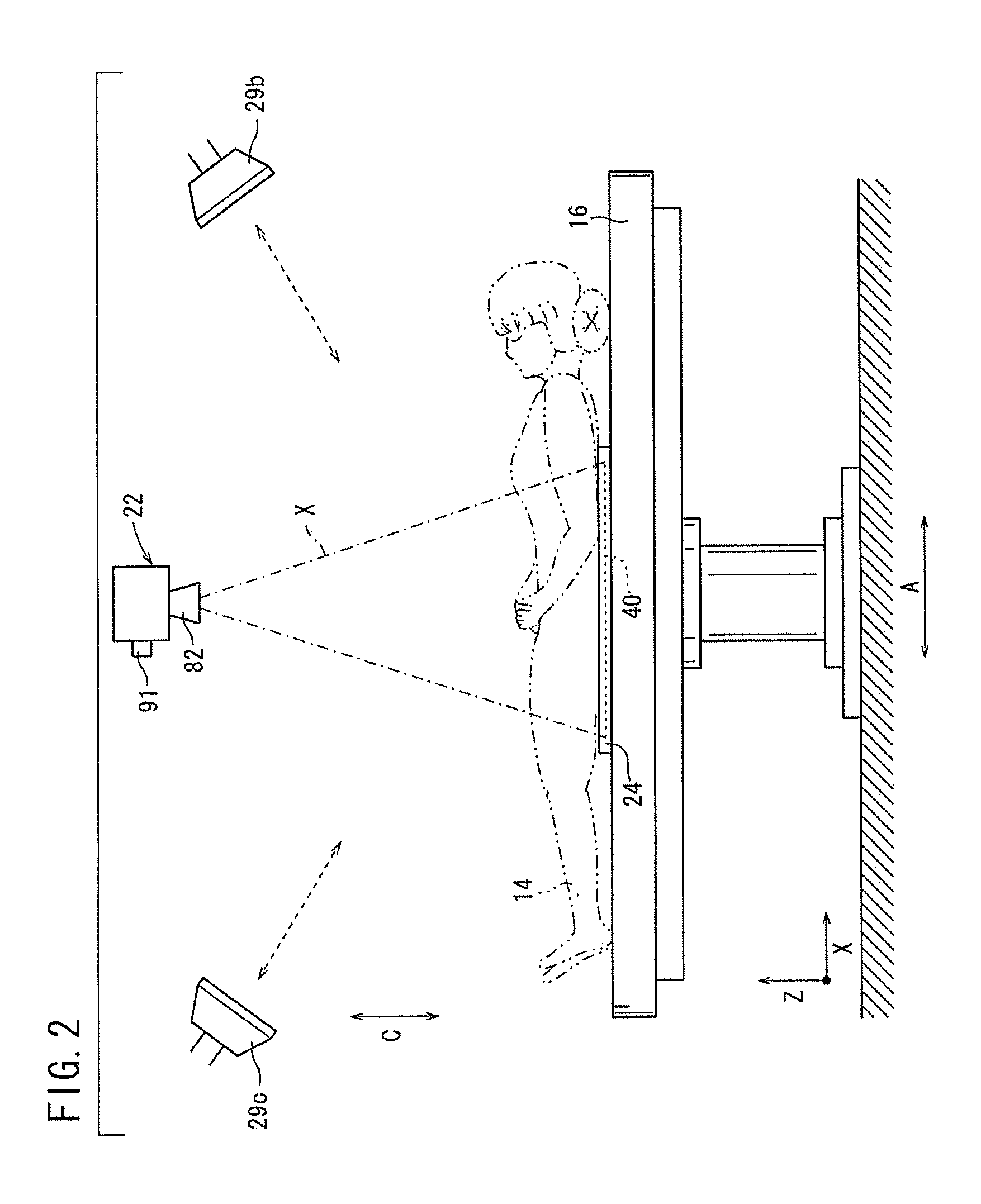
[0035]FIGS. 1 through 3 show an operating room 12 incorporating a radiation image capturing system 10 according to the present invention. As shown in FIG. 1, the operating room 12 has, in addition to the radiation image capturing system 10, a surgical table 16 for a patient 14 to lie thereon, and an instrument table 20 disposed to one side of the surgical table 16 for placing thereon various tools and instruments to be used by surgeons 18 for operating the patient 14. The surgical table 16 is surrounded by various apparatus required for surgical operations, including an anesthesia apparatus, an aspirator, an electrocardiograph, a blood pressure monitor, etc.
[0036]The radiation image capturing system 10 includes an image capturing apparatus (image capturing unit) 22 for irradiating the patient 14 with a radiation X at a dosage according to image capturing conditions, a radiation detecting cassette 24 housing therein a radiation detector (radiation conversion panel) 40, to be describe...
second embodiment
[0136]In the radiation image capturing system 600 as shown in FIGS. 16 and 19A, the light-emitting part 604 of the orientation detecting unit 602 emits light toward the radiation detecting cassette 24 (in the direction indicated by the arrow E), the reflection portion 612 formed on the casing 34 reflects the emitted light, and the reflected light returns toward the orientation detecting unit 602 (in the direction indicated by the arrow D) so as to allow the light-receiving part 606 to receive the reflected light. Specifically, a part of reflection portion 612 which is not covered by the patient 14 reflects the emitted light to the light-receiving part 606 (in the direction indicated by the arrow D). That is, the reflection portion 612 is formed on the flat plate portion 608a near the walls 610a to 610d of the casing 34 in order to avoid the patient 14 lying on the irradiated surface 36.
[0137]Then, based on the detection results obtained by the orientation detecting unit 602, a dete...
third embodiment
[0144]Next, with reference to FIGS. 20 to 23, a radiation image capturing system 700 according to the invention shall be explained. Structural elements thereof which are the same as those of the radiation image capturing systems 10, 600 are designated with the same reference numerals and detailed explanations of such features shall be omitted.
[0145]In the radiation image capturing system 700, as shown in FIGS. 20 and 21, the radiation detecting cassette 24 is placed on the surgical table 16 on which the patient 14 is lying. The grid 38, the radiation detector 40, and the lead plate 42 are not disposed in the four corners of the radiation detecting cassette 24, but signal generators 702 are disposed respectively in the four corners of the radiation detecting cassette 24. A signal detector 704 is disposed in the image capturing apparatus 22, correspondingly to the four signal generators 702 (see FIG. 22). The signal detector 704 of the image capturing apparatus 22 detects signals from...
PUM
 Abstract
Description
Claims
Application Information
 - R&D
- Intellectual Property
- Life Sciences
- Materials
- Tech Scout
- Unparalleled Data Quality
- Higher Quality Content
- 60% Fewer Hallucinations
Browse by: Latest US Patents, China's latest patents, Technical Efficacy Thesaurus, Application Domain, Technology Topic, Popular Technical Reports.
© 2025 PatSnap. All rights reserved.Legal|Privacy policy|Modern Slavery Act Transparency Statement|Sitemap|About US| Contact US: help@patsnap.com


