Multi-battery charger

a multi-battery, charger technology, applied in the field of chargers, can solve the problems of inconvenience for users of cellular phones charging practice, improper recharge of rechargeable batteries, and type of conventional chargers

Inactive Publication Date: 2011-03-01
LAW HUNG HI
View PDF2 Cites 4 Cited by
  • Summary
  • Abstract
  • Description
  • Claims
  • Application Information

AI Technical Summary

Benefits of technology

[0008]A main object of the present invention is to provide a multi-battery charger which is capable of charging battery of different sizes, and irrespective of polarity of the battery terminals. In other words, the multi-battery charger of the present invention is universal in the sense that it is adapted to charge a wide variety of different kinds of rechargeable batteries in an extremely convenient manner.
[0009]Another object of the present invention is to provide a multi-battery charger comprising a multi-battery charging module adapted to accurately and effectively detect the correct polarity of a rechargeable battery which is electrically contacting with the multi-battery charger without damaging either the multi-battery charger or the rechargeable battery. Thus, the present invention ensures that the charging process is safe and non-destructive to any electrical devices involved.
[0010]Another object of the present invention is to provide a multi-battery charger which is adapted to effectively and efficiently recharge a wide variety of rechargeable batteries without needing to affect conventional electrical and physical structure of the rechargeable batteries so as to promote extensive application of the present invention.
[0015]a polarity detection circuitry electrically connected with the recharging circuitry to accurately detect a positive polarity and a negative polarity of the first and the second battery terminal when the first and the second battery terminals are electrically connected with two of the charging terminals, in such a manner that when a correct polarity of the first and the second battery terminals is determined, the recharging circuitry is activated to properly recharge the rechargeable battery.

Problems solved by technology

There exist several disadvantages for this type of conventional charger.
This presents an inconvenience charging practice to users of cellular phones and creates a potentially dangerous scenario when the users accidentally or carelessly put the rechargeable battery into the charging slot in reverse polarity.
In such a case, the rechargeable battery may not be properly recharged, and in the worst scenario, the rechargeable battery may even have the possibility of having explosion.
Second, almost all conventional chargers have been specifically designed to recharge only one particular type or model of rechargeable batteries.
Rechargeable batteries of other types simply cannot be inserted into the battery slot for electrically connecting the battery terminals with the charging pins.
This presents an undue inconvenience to cellular phone users.
However, the main problem of this type of battery charger is that each particular battery slot is usually designed for charging a particular type of battery having a particular capacity.
Thus although this type of battery charger mitigates some of the disadvantages mentioned above, it does not resolve the relevant problems acceptably because it does not address the core nature of the problem, i.e. the inherent inflexible nature of conventional chargers.
Thus, when a battery of unmatched capacity is put into one particular battery slot, either the rechargeable battery or the charging circuitry may be severely damaged.

Method used


Image

  • Multi-battery charger
  • Multi-battery charger
  • Multi-battery charger

Examples


Embodiment Construction

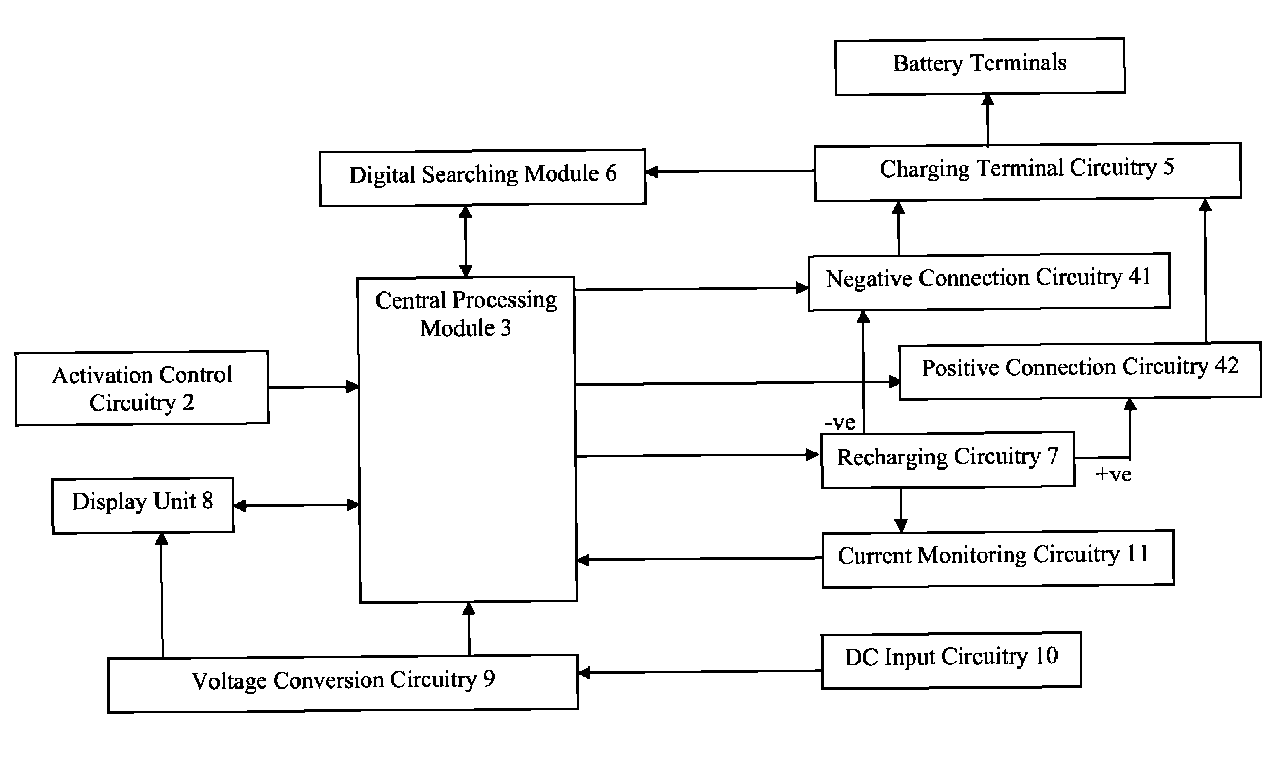
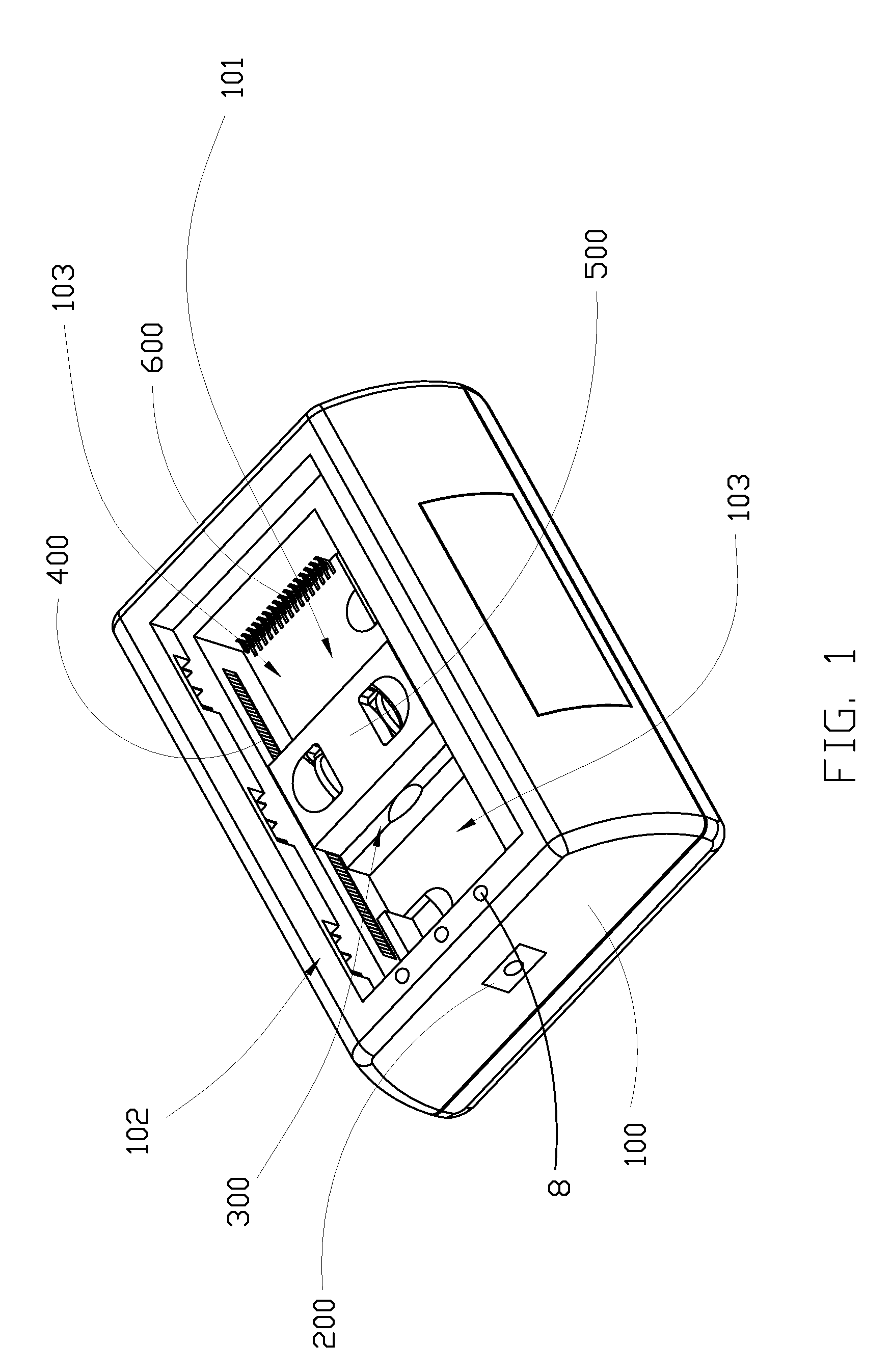
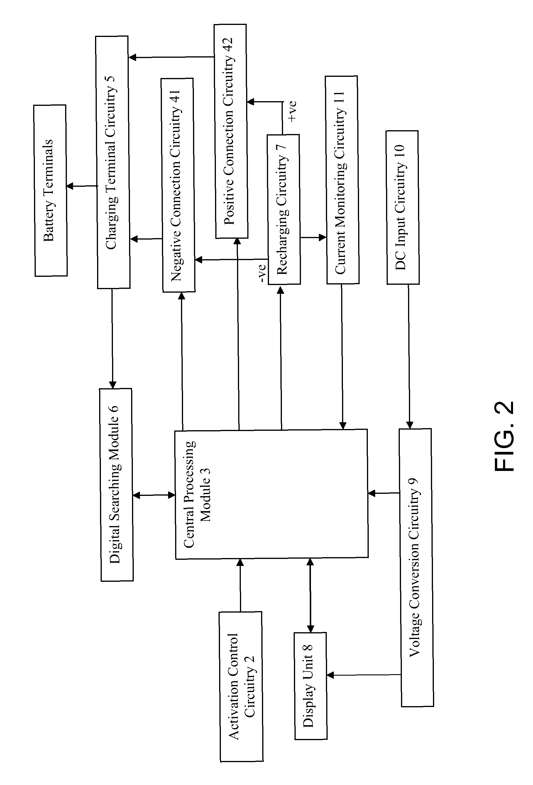
[0029]Referring to FIG. 1 to FIG. 3, FIG. 4A to FIG. 4F of the drawings, a multi-battery charger according to a preferred embodiment of the present invention is illustrated, in which the multi-battery charger comprises a charger case 100, and a multi-battery charging module. The multi-battery charger is for charging at least one rechargeable battery, such as a rechargeable battery for a conventional cellular phone, and has a first and a second battery terminal.

[0030]The charger case 100 comprises a plurality of electrically neutral charging terminals 600 spacedly provided thereon as multi-contact terminals of the charger case 100, and an electric input terminal 200 adapted for electrically connecting with an external DC power source.

[0031]The multi-battery charging module is provided in the charger case 100 to electrically communicate with the charging terminals 600, and comprises a recharging circuitry 7 and a polarity detection circuitry. The recharging circuitry 7 has a positive ...


PUM


Abstract

A multi-battery charger for at least one rechargeable battery includes a charger case, and a multi-battery charging module. The charger case includes a plurality of electrically neutral charging terminals spacedly provided thereon, and an electric input terminal adapted for electrically connecting with an external DC power source. The multi-battery charging module is provided in the charger case to electrically communicate with the charging terminals, and includes a recharging circuitry and a polarity detection circuitry. The polarity detection circuitry is electrically connected with the recharging circuitry to accurately detect a positive polarity and a negative polarity of the first and the second battery terminal when the first and the second battery terminals are electrically connected with two of the charging terminals, in such a manner that when a correct polarity of the first and the second battery terminals is determined, the recharging circuitry is activated to properly recharge the rechargeable battery.

Description

BACKGROUND OF THE PRESENT INVENTION[0001]1. Field of Invention[0002]The present invention relates to a charger, and more particularly to a multi-battery charger which is capable of charging battery of different sizes, and irrespective of polarity of the battery terminals.[0003]2. Description of Related Arts[0004]A conventional charger, such as a conventional battery charger for a cellular phone battery, usually comprises a charger case having a battery slot formed thereon, a positive charging pin and a negative charging pin spacedly provided within the battery slot for aligning with a battery terminal and a negative battery terminal of the battery respectively, and a charging circuitry provided within the charger case to electrically connect with the positive charging pin and the negative charging pin. When the battery is is placed properly within the battery slot, the charging circuitry can be activated to start charging of the battery through the positive charging pin and the nega...

Claims


Application Information

Patent Timeline
Patent Type & Authority Patents(United States)
IPC IPC(8): H02J7/00
CPCH02J7/0003H02J7/0045H02J7/00047
Inventor LAW, HUNG HI
Owner LAW HUNG HI
Why Eureka
Try Eureka