Reversible casing cutter

a cutter and casing technology, applied in the direction of drilling machine and method, drilling accessories, drilling holes/wells, etc., can solve the problems of painstaking process, time-consuming and laborious, and cutter blade damage of conventional tools,

Inactive Publication Date: 2011-03-22
ABRADO
View PDF6 Cites 29 Cited by
  • Summary
  • Abstract
  • Description
  • Claims
  • Application Information

AI Technical Summary

Benefits of technology

[0009]It is, therefore, an object of the present invention to provide a casing cutter that can be used for severing multiple tubulars below the mud line.
[0010]It is another object of the present invention to provide a casing cutter that can be used for cutting various diameter tubulars that have been cemented together in an expeditious and relatively inexpensive manner.
[0012]These and other objects of the present invention are achieved through a provision of an apparatus and method for severing multiple tubulars in a well bore. The apparatus has a hollow support body of a generally cylindrical configuration and an outside diameter smaller than the inner diameter of the innermost of the tubulars. The support body has a longitudinal slot extending through diametrically opposite location of the support body. The ends of the support body are provided with external threads allowing reversible engagement of the support body to a downhole work string.

Problems solved by technology

If the inner casing collapses, the job becomes even more complicated and the casing needs to be drilled out or severed by an explosive to remove the smallest diameter casing.
The cutter blades of a conventional tool are often damaged, requiring pulling the tool to the surface and starting the process again.
The painstaking process takes several days over the use of conventional tools.
If the inner casing collapsed, it may become completely impossible to mill out the necessary portions of the tubulars.
Such procedure is also expensive and takes several days.
While the tool of the '155 patent works satisfactory, it was observed during the tests that the cutter blades or the pivot pins carrying the blades sometimes become damaged, which requires that the tool be repaired with new blades or new pivot pins.
Naturally, the blade or pin replacement takes time, which slows the casing cutting process.

Method used


Image

  • Reversible casing cutter
  • Reversible casing cutter
  • Reversible casing cutter

Examples


Embodiment Construction

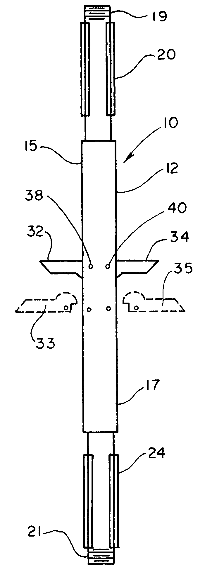
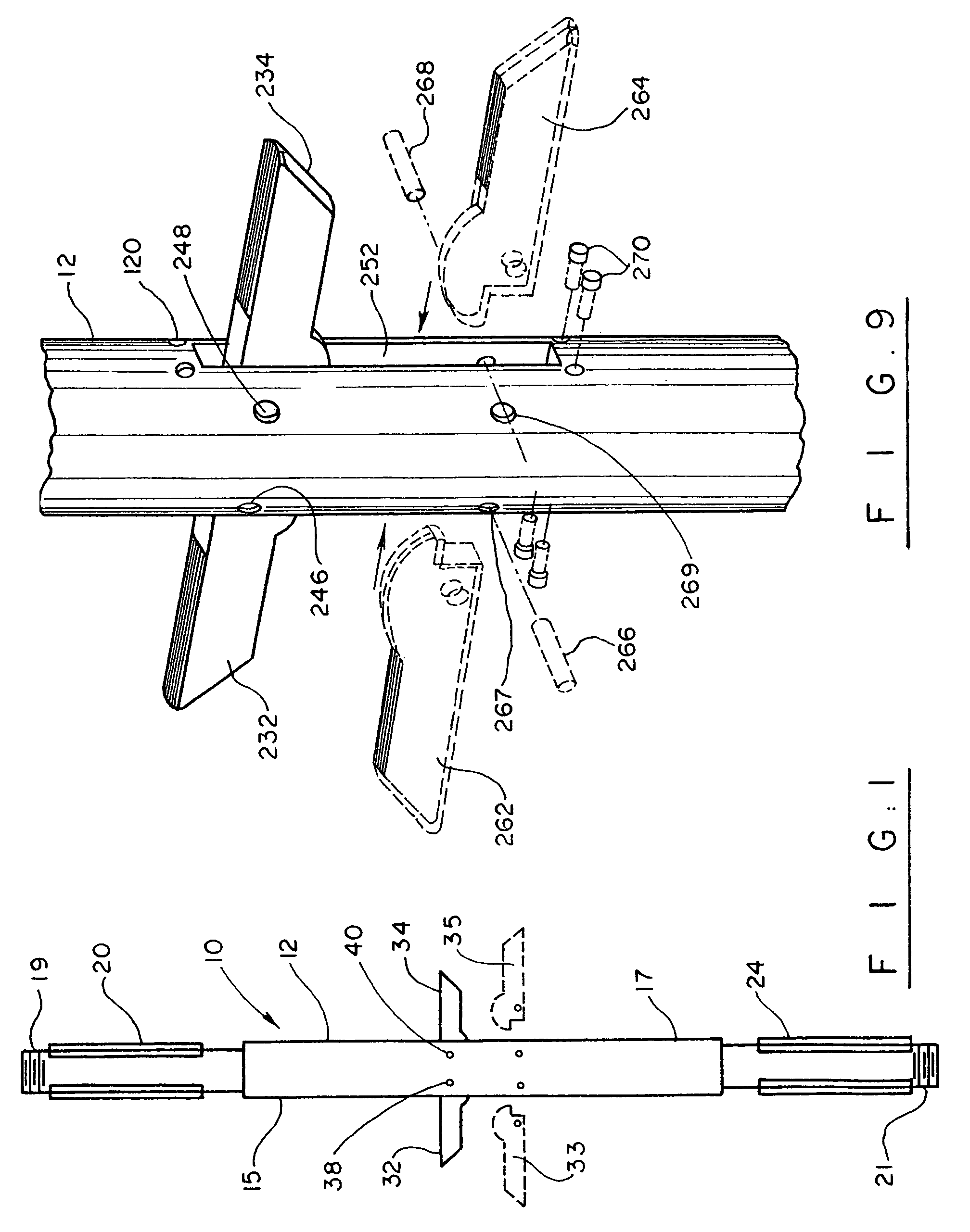
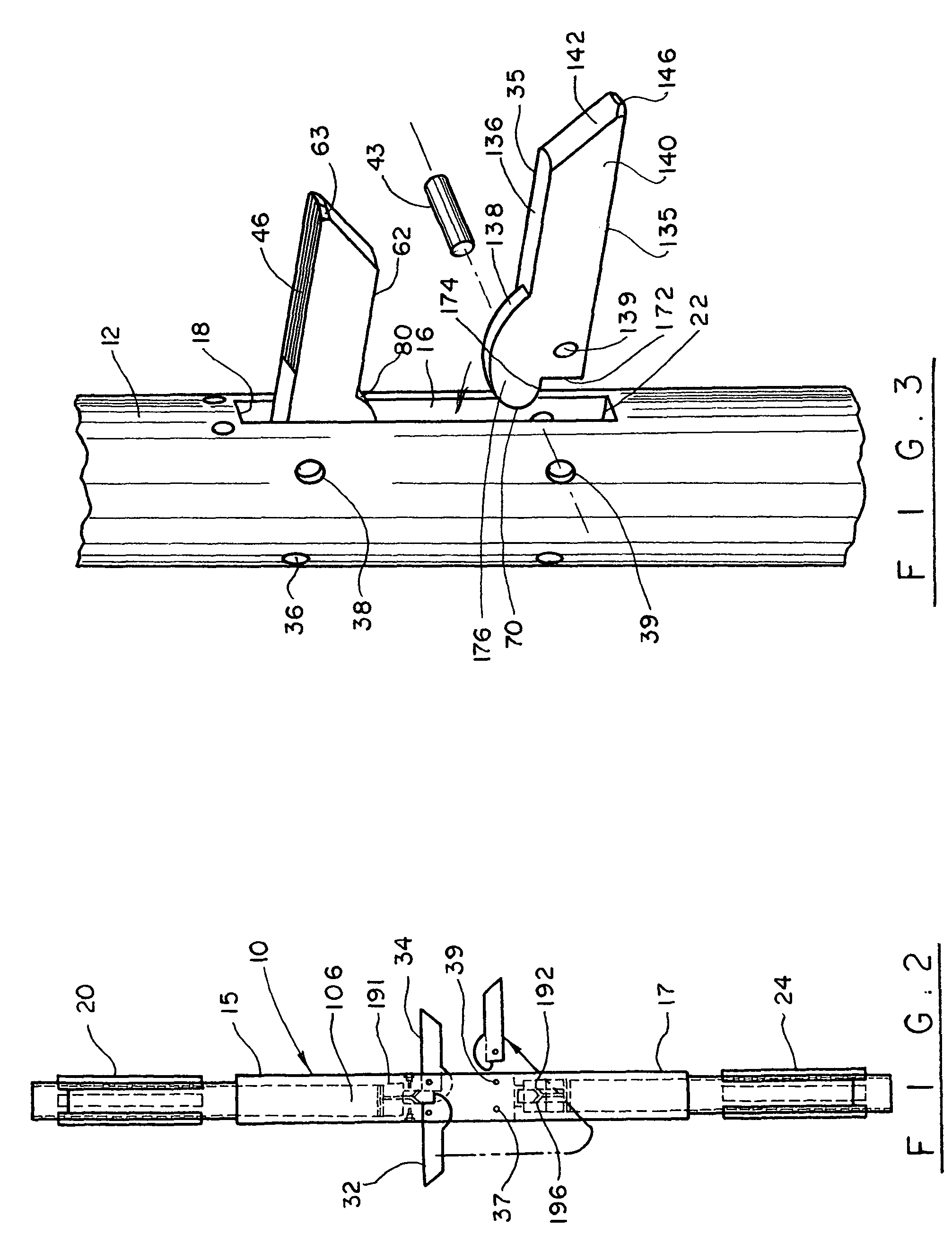
[0029]Turning now to the drawings in more detail, numeral 10 designates the cutting tool in accordance with the present invention. The cutting apparatus 10 comprises a cutter body 12 configured as an elongated hollow body with a pair of longitudinal slots 14 and 16 formed in the side wall of the body 12. The slots 14 and 16 are open to the interior of the body 12, forming a through opening that communicates with diametrically opposite sides of the cylindrical side wall. An upper annular shoulder 18 is formed above the slots 14 and 16. A lower shoulder 22 is formed below the slots 14 and 16.

[0030]An optional magnet retrieval tool 20 can be detachably secured to a first end 15 the tool body 12 and a second optional magnet retrieval tool 24 can be secured to the second end 17 of the tool body 12. The ends 15 and 17 of the body 12 are provided with threaded subs 19, 21, respectively allowing connecting of the cutter body 12 to a string (not shown) that lowers the tool body 12 into a wel...


PUM


Abstract

Casing cutter for severing multiple tubulars in a well bore has a pair of cutter blades pivotally mounted on a support body. The blades are pivotally mounted for gradual movement outside of the support body when downward force is applied to proximate ends of the cutter blades. The support body is rotated inside the innermost of the multiple tubulars, while the cutter blades sever the tubulars of progressively increasing diameter. Should the cutter blades or pivotal connections become unusable, the tool body can be rotated about the vertical axis and secured to a downhole string by the opposite end. A substitute pair of cutter blades are then engaged on the tool body and operated to cut the casings similar to the first set of the cutter blades.

Description

FIELD OF THE INVENTION[0001]The present invention relates to the field of gas and petroleum exploration and production and, more particularly, to an apparatus for cutting multiple tubulars, such as casings in a well bore.BACKGROUND OF THE INVENTION[0002]In the offshore industry, the exploration and production of gas and petroleum is conducted through tubulars of various diameters that are cemented inside each other and extend to a distance below the sea floor, where the production zone is located. When the well is abandoned, the owner of the offshore rig is required to remove the casing at the depth of 20 feet below the mud line. After the casing is cut, the rig owner must cement the plug on the abandoned well to protect the marine life in the surrounding area.[0003]To perform the cutting operation below the mud line, a cutting tool is lowered into the innermost casing, which usually has a relatively small diameter, and severs the tubulars. When the first inside casing is removed, a...

Claims


Application Information

Patent Timeline
Patent Type & Authority Patents(United States)
IPC IPC(8): E21B29/00
CPCE21B29/005
Inventor BRYANT, JR., CHARLES LARUERUTTLEY, DAVID J.
Owner ABRADO
Why Eureka
Try Eureka