
Lighting apparatus

a technology of lighting apparatus and overhead lights, which is applied in the direction of vehicle spotlighting, vehicle lighting, and mass transit vehicle lighting, etc., can solve the problems of difficult access for passengers, limited range of movement and/or adjustment, and individual overhead lights, etc., and achieve the effect of improving the appearance of the cabin

Inactive Publication Date: 2011-03-22
BE AEROSPACE INCORPORATED
View PDF41 Cites 28 Cited by
  • Summary
  • Abstract
  • Description
  • Claims
  • Application Information

AI Technical Summary

Benefits of technology

The present invention is a lighting apparatus with a flexible housing that can be pivoted between a stored position and a deployed position. The housing can flex transversely in response to an applied force, such as if it is bumped or jarred by a passenger or other object. The housing has a swivel portion that can change the direction of the light, and various electrical features such as an auto-off feature and a dimmable feature. The housing can be adjusted and maintained at a plurality of desired positions through the interaction of a plurality of detents and complementary recesses or notches. The invention provides a quiet lighting apparatus that is capable of remaining in a fixed position and improves the appearance of the cabin by providing a stowed position for unused lights.

Problems solved by technology

Problems exist with such individual overhead lights.
For example, they generally have a very limited range of movement and / or adjustment and are generally not easily accessible by passengers.
Flexible arm lighting fixtures solve the mobility problems related to the overhead lights; however, they also present new problems.
For example, flexible arm lighting fixtures are not as aesthetically pleasing as the overhead lights, and flexible arms typically are unable to maintain a desired position.
In addition, they can be noisy and difficult to stow away.
This solution, however, creates additional problems in keeping the flexible arm in the desired position and can cause unwanted movement of the arm.

Method used


Image

  • Lighting apparatus
  • Lighting apparatus
  • Lighting apparatus

Examples


Embodiment Construction

[0024]The present invention will now be described more fully with reference to the accompanying drawings in which exemplary embodiments of the invention are shown.

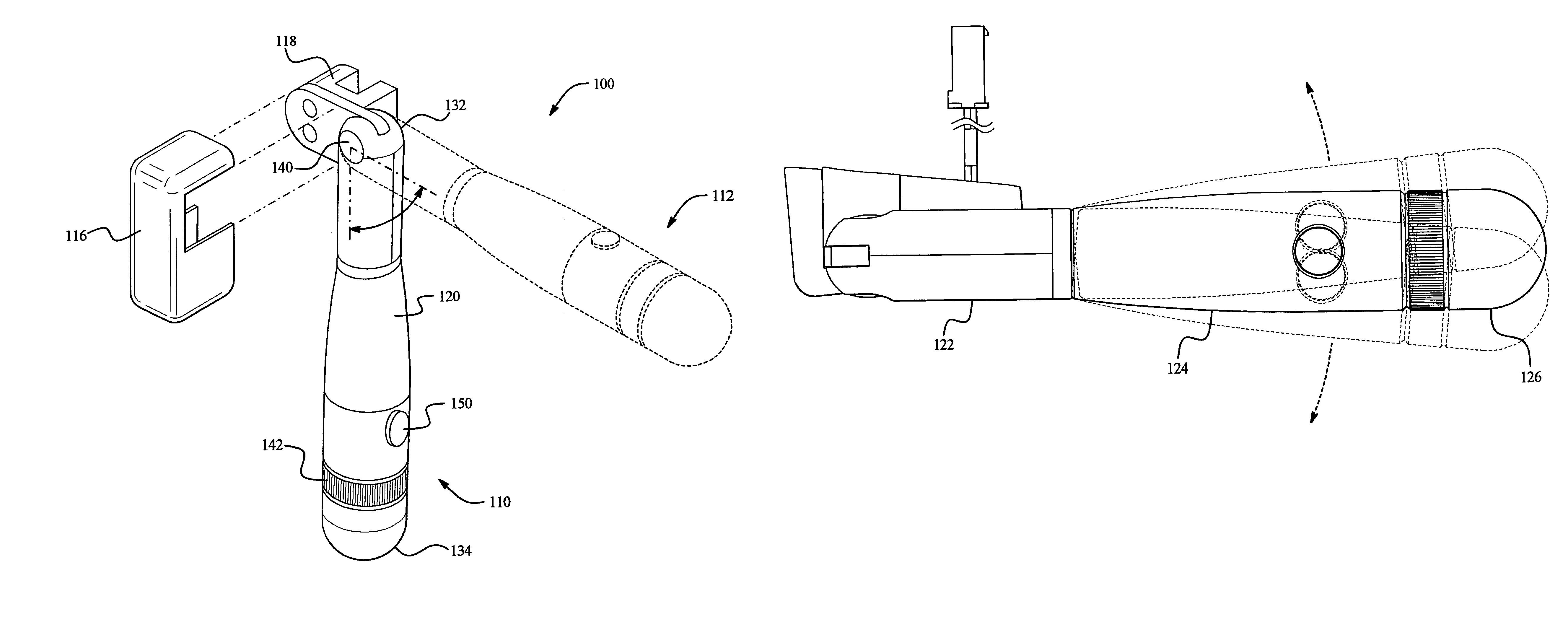
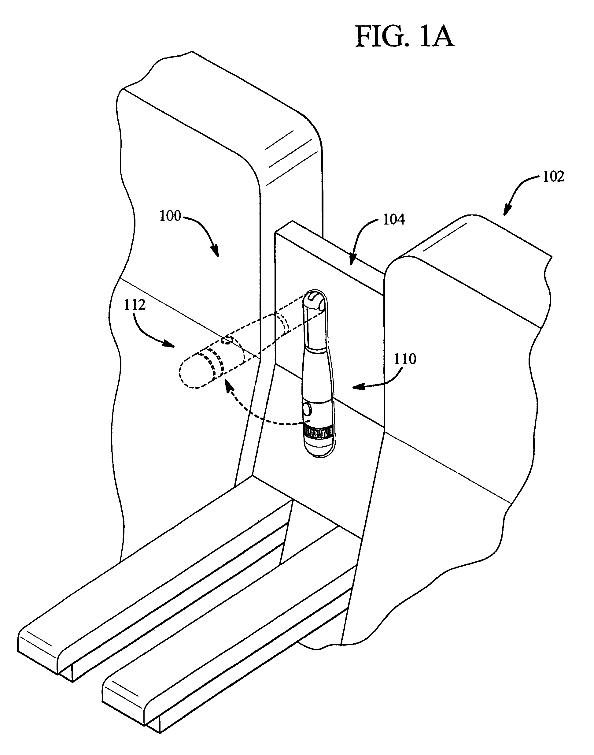
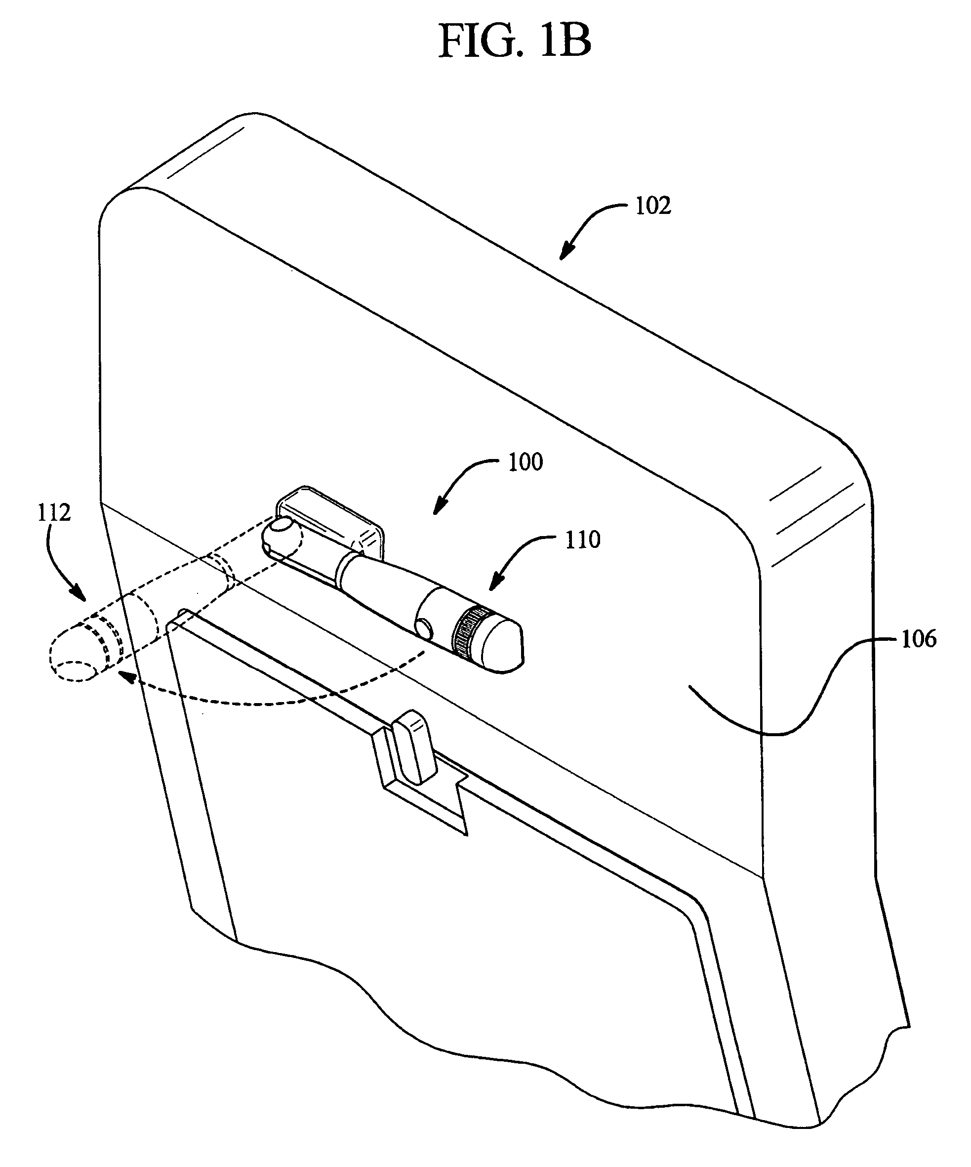
[0025]As shown in FIGS. 1A-10, various embodiments of the present invention provide a lighting apparatus 100. In an embodiment, the lighting apparatus 100 may be coupled to a seating apparatus 102. For example, in an embodiment, the lighting apparatus 100 may be used with a seating apparatus 102 on a passenger vehicle such as an airplane, bus, yacht, or automobile. The lighting apparatus 100 may be coupled to the seating apparatus 102 in any suitable location. For example, in an embodiment, the lighting apparatus 100 may be coupled to a seat shell portion 104 of the seating apparatus 102, as shown in FIG. 1A. The lighting apparatus 100 may also be coupled to a seat back 106 to provide light for a passenger in the row behind the seat, as shown in FIG. 1B, or to a seat side 108 wherein the deployed lighting apparatus 100 pro...


PUM


Abstract

The present invention provides a lighting apparatus with an elongated housing which accommodates a light source. The housing may be pivoted to rotate between a stored position and a deployed position. The housing may be maintained at a plurality of desired positions within its range of rotation. In addition, according to a feature of the invention, the elongated housing may be relatively rigid, yet also articulated, so that it can flex transversely in response to an applied force. In an embodiment, the housing may be provided with a swivel portion that can be used to change the direction of the light. Various electrical features may be provided as well, such as a brightness control feature and an auto-off feature that switches off the light in the stowed position.

Description

CROSS-REFERENCE TO RELATED PATENT APPLICATIONS[0001]This patent application claims the benefit of U.S. Provisional Patent Application No. 60 / 617,411, filed Oct. 8, 2004, which is herein incorporated by reference.FIELD OF THE INVENTION[0002]This invention pertains to a lighting apparatus. More particularly, this invention relates to a lighting apparatus that is adjustable, durable, and stowable.BACKGROUND OF THE INVENTION[0003]Many passenger vehicles include light sources for passenger use. For example, reading lights are frequently included in automobiles, buses, trains, and aircraft. In most passenger vehicles the light sources for passengers are provided overhead. Overhead lighting also is typically used to provide light for seating areas in situations outside of passenger vehicles, e.g., at a desk. In passenger vehicles, light sources are frequently individual overhead lights designed to provide light only for the person seated below the light. Problems exist with such individual...

Claims


Application Information

Patent Timeline
Patent Type & Authority Patents(United States)
IPC IPC(8): F21S8/00B60Q1/06F21V21/00F21L4/04F21L4/00
CPCB60Q3/001B60Q3/0223B60Q3/0253B60Q3/0263B60Q3/0266B60Q3/0286B60Q3/0293B60Q3/0296F21V21/26F21W2101/08B60Q3/82B60Q3/85B60Q3/233B60Q3/44B60Q3/56B60Q3/57B60Q3/76B60Q3/80F21W2106/00
Inventor CHOU, JOHNSCHMIDT, GLENN T.ZENG, SAMUELGRUMET-AVALLONE, AMYGREENFIELD, THOMASGLOISTEN, JENNIFER L.
Owner BE AEROSPACE INCORPORATED
Learn More