Wedge of a cable connector grounding device

a grounding device and cable connector technology, applied in the direction of coupling device details, coupling device connection, connection contact member material, etc., can solve the problems of poor tightness and clearance, and the effect of grounding is not achieved

Active Publication Date: 2011-03-22
LEE CHUN TE
View PDF4 Cites 6 Cited by
  • Summary
  • Abstract
  • Description
  • Claims
  • Application Information

AI Technical Summary

Problems solved by technology

Further, when being subject to a force and pulled and dragged, the lead wire 6 glides along the arc-shaped slot 7, there being thereby the possibility of poor tightness and clearance.
Apparently, the effect of grounding is not achieved.

Method used


Image

  • Wedge of a cable connector grounding device
  • Wedge of a cable connector grounding device
  • Wedge of a cable connector grounding device

Examples


Embodiment Construction

[0018]Now, the present invention will be described more specifically with reference to the following embodiments. It is to be noted that the following descriptions of preferred embodiments of this invention are presented herein for purpose of illustration and description only; it is not intended to be exhaustive or to be limited to the precise form disclosed.

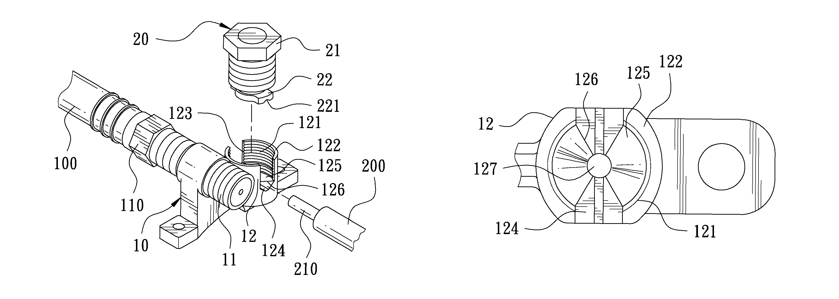
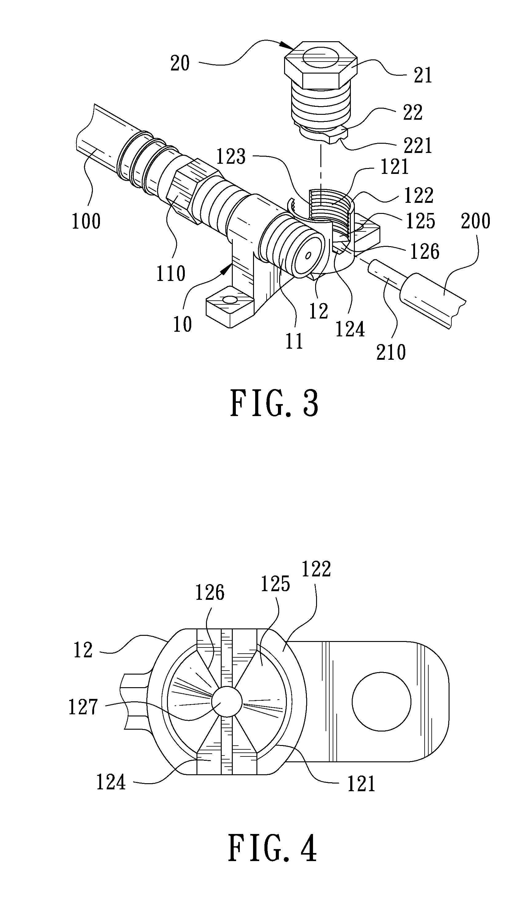
[0019]With reference to FIGS. 3 and 4 shown respectively as a partially exploded 3D view of a cable connector according to this invention and as a top view of a spirally conjunct seat, this invention mainly comprises a body 10 and a packing unit 20.

[0020]The body 10 is provided with two male joints 11 connected to each other, and the male joints 11 can be spirally conjunct to female joints 110 of two cables 100. One side of the body 10 is formed with a spirally conjunct seat 12. A concave spirally conjunct slot 121 is formed in the spirally conjunct seat 12 and a circumferential wall 122 is defined around the circumference of sp...


PUM


Abstract

A wedge of a cable connector grounding device includes a body. One side of the body is formed with a spirally conjunct seat inside which a concave spirally conjunct slot is formed. Two concave slots opposite to each other are formed. At the bottom of spirally conjunct slot, a position limiting groove is formed from the concave slots towards the center and a concave camber is formed along the circumferential wall toward the center. A wedge crest line is defined at a section of connection between the concave camber and the position limiting groove. A packing unit is provided and spirally connected to the spirally conjunct slot. The packing unit may be used to tighten the lead wire passing through the position limiting groove for achievement of the longitudinal position limiting. The wedge crest lines are used to wedge the lead wire transversally and tighten the lead wire.

Description

BACKGROUND OF THE INVENTION[0001]1. Field of the Invention[0002]This invention relates to a wedge of a cable connector grounding device.[0003]2. Description of the Prior Art[0004]With reference to FIG. 1, a 3D view of a conventional cable central connector, the cable connector mainly comprises a body 1. One side of the body 1 is formed with a spirally conjunct seat 2 inside which a concave tapped hole 3 is formed. Then, on the circumferential wall of spirally conjunct seat 2, two concave slots 4 opposite to each other are formed axially for a lead wire 6 of a grounding wire 5 to pass into. Further, an arc-shaped slot 7 conjunct to the slots 4 is formed at the bottom of tapped hole 3. Next, a packing seat 8 is spirally conjunct to the tapped hole 3, and a concave arc-shaped slot 9 is further formed at the bottom of packing seat 8.[0005]With reference to FIG. 2, a schematic view illustrating the service of conventional cable central connector, although the conventional cable connector...

Claims


Application Information

Patent Timeline
Patent Type & Authority Patents(United States)
IPC IPC(8): H01R4/66
CPCH01R4/66
Inventor LEE, CHUN-TE
Owner LEE CHUN TE
Why Eureka
Try Eureka