Aircraft vision system with relief lines and associated method

a technology of aircraft vision and relief lines, applied in the field of aircraft vision systems, can solve the problems of inaccurate type of image obtained, insufficient clearness of pilot's type of image, and inability to accurately identify aircraft, etc., and achieve the effect of improving the analysis of terrain

Active Publication Date: 2014-04-10
DASSAULT AVIATION
View PDF8 Cites 5 Cited by
  • Summary
  • Abstract
  • Description
  • Claims
  • Application Information

AI Technical Summary

Benefits of technology

[0022]One aim of the invention is therefore to obtain a vision system that improves the analysis of t...

Problems solved by technology

Such vision systems provide substantial assistance to pilots, but are sometimes inaccurate, in light of possible errors in the positioning of the aircraft and/or in the topographical data available in the databases.
The existing vision systems are effective, but have s...

Method used


Image

  • Aircraft vision system with relief lines and associated method
  • Aircraft vision system with relief lines and associated method
  • Aircraft vision system with relief lines and associated method

Examples


first embodiment

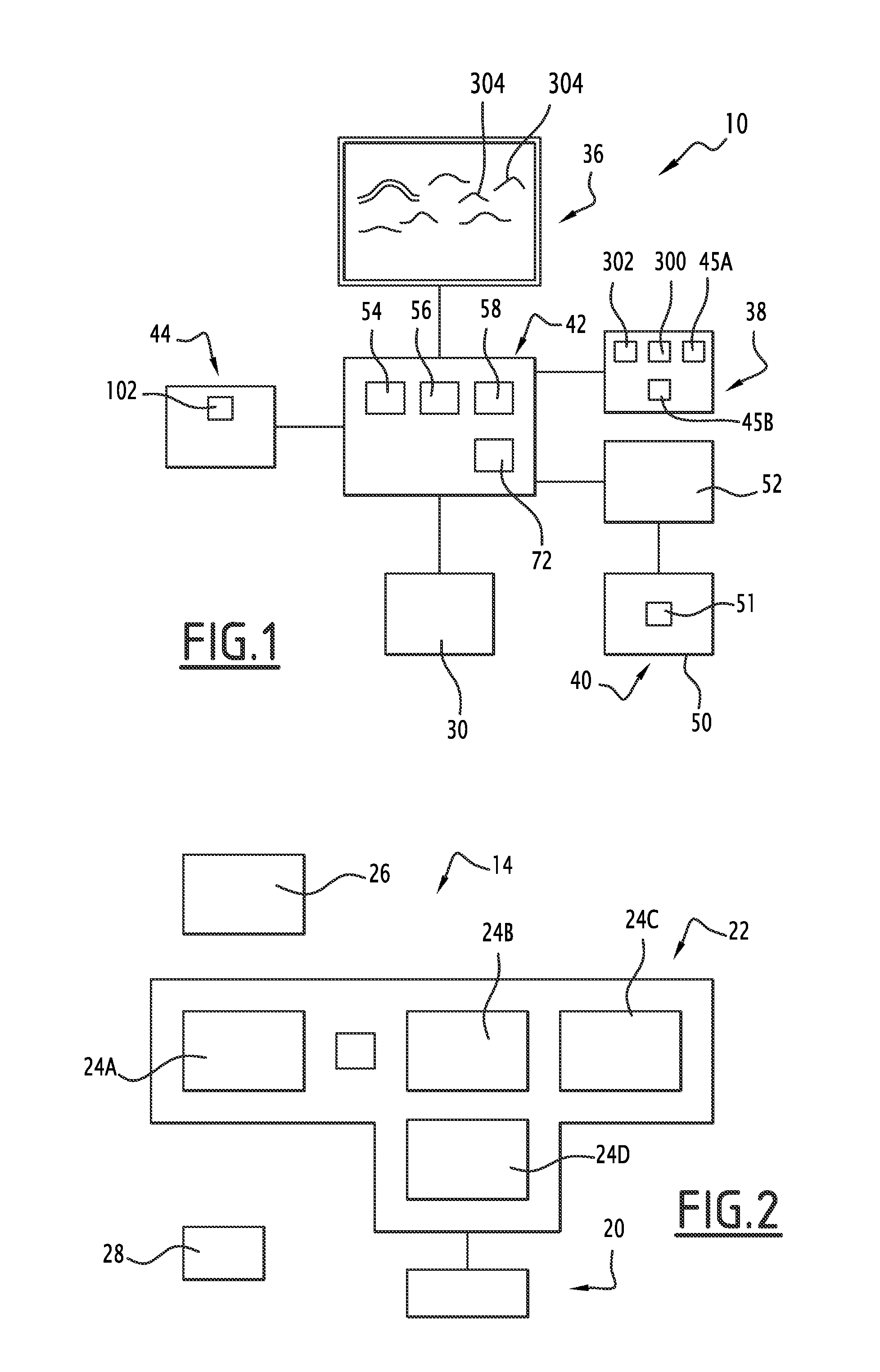
[0068]In a first embodiment that will be described hereafter, the display 36 of the vision system 10 according to the invention is the semitransparent head-up display 26 of the cockpit 14.

[0069]In that case, the display 36 can be made partially transparent to allow viewing of the environment situated in front of the display 36, transparently. The display 36 can be made at least partially opaque by displaying a synthetic environment or real images generated by one of the generating assemblies 38, 40, and provided by the management assembly 42, as will be described below.

[0070]The dimensions of the display 36 correspond to an observation volume 44A in the space situated in front of the aircraft 12, defined substantially by a pyramid. In reference to FIG. 5 and FIG. 6, the observation volume 44A has a vertical opening angle, along a vertical axial plane of the aircraft 12, equal to A1 and a horizontal opening angle equal to A2 in a horizontal axial plane of the aircraft 12 in a referen...

second embodiment

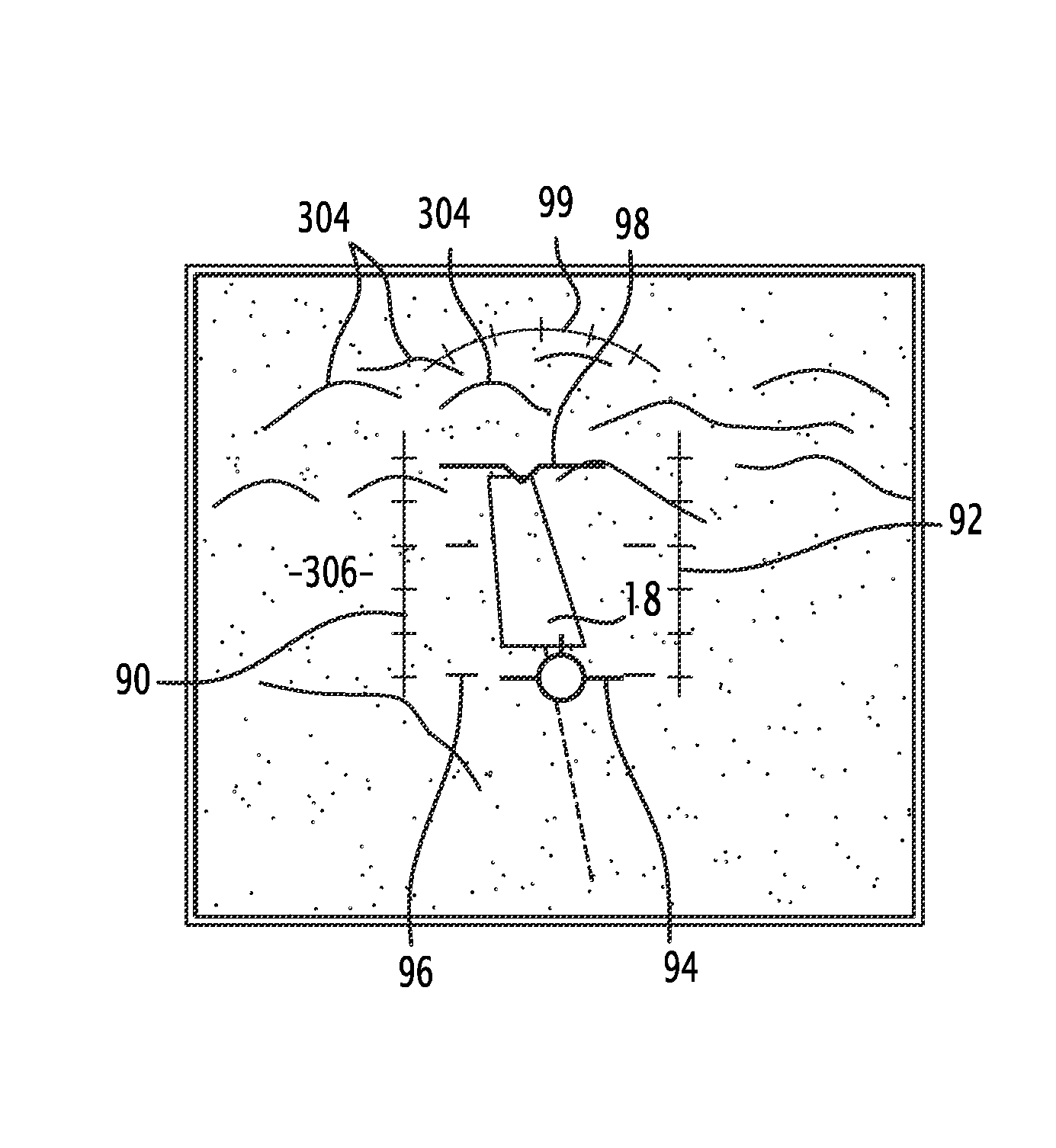
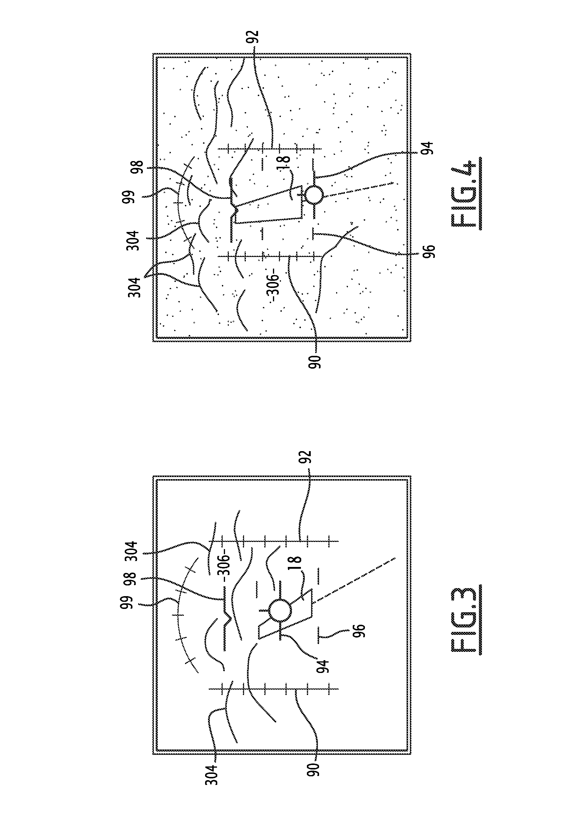
[0132]In a second embodiment illustrated in FIG. 4, the management assembly 42 displays, simultaneously with the relief lines 304, a real image obtained from image data received from the real image generating assembly 40. The real image therefore appears in the intermediate areas 306 between the relief lines 304.

[0133]Advantageously, the relief lines 304 are superimposed on the real image.

[0134]To that end, the real image generating assembly 40 takes, at each moment T, image data in front of the aircraft 12, representative of the environment situated in front of said aircraft 12.

[0135]Then, this image data is transferred to the module 52 to be converted into a real image. The management assembly 42 then displays a real image obtained in at least part of the intermediate areas 306, which appears visible between the relief lines 304.

[0136]The relief lines 304 thus added to the real image emphasize the relief elements present on the real image, to assist the pilot in interpreting data ...


PUM


Abstract

The vision system for an aircraft according to the invention comprises a display management system, on a display, capable of dynamically displaying synthetic information coming from a synthetic environment generating assembly on the display. The management assembly can control the display, on a first region of the display, of relief lines representative of the terrain situated facing the aircraft, without displaying synthetic surface representations of the terrain in the intermediate areas situated between the relief lines of the first region of the display. The generating assembly includes means for determining the position of the crest lines of the terrain from topographical data present in at least one database, and means for computing the position of the relief lines from the position of the crest lines of the terrain.

Description

CROSS-REFERENCE TO RELATED APPLICATIONS[0001]This application claims benefit of French patent application serial number FR 12 02676, filed Oct. 5, 2012, which is herein incorporated by reference.BACKGROUND OF THE INVENTION[0002]1. Field of the Invention[0003]The present invention relates to a vision system for an aircraft, comprising:[0004]a display;[0005]an assembly for generating a synthetic environment, the generating assembly including a database, containing at least topographical information relative to the terrain situated facing the aircraft;[0006]a display management system, on the display, capable of dynamically displaying synthetic information coming from the generating assembly on the display.[0007]2. Description of the Related Art[0008]Such a system is designed to be installed in the cockpit of an aircraft to be associated with a display of the cockpit. The display is for example an at least partially transparent display, such as a semitransparent screen placed in front ...

Claims


Application Information

Patent Timeline
IPC IPC(8): B64D45/00
CPCB64D45/00G06T19/006G01C23/00
Inventor BAUDSON, OLIVIERTURPIN, ARNAUD
Owner DASSAULT AVIATION
Why Eureka
Try Eureka