Screw for osteosynthesis and arthrodesis

a technology of arthrodesis and screws, which is applied in the direction of internal osteosynthesis, osteosynthesis devices, fasteners, etc., can solve the problems of screw weakening, easy breakage of teeth thus defined, and inability to achieve good penetration at the cylindrical end

Active Publication Date: 2016-11-29
STRYKER EURO OPERATIONS HLDG LLC
View PDF108 Cites 4 Cited by
  • Summary
  • Abstract
  • Description
  • Claims
  • Application Information

AI Technical Summary

Benefits of technology

[0023]For this purpose, the invention therefore notably proposes an osteosynthesis and arthrodesis screw for orthopedic surgery notably of the hand and of the foot, the screw being tubular or not, having along its main axis (AP) three successive portions, namely a distal portion comprising threads (A1), a smooth central portion or central barrel (f) and a proximal portion or head comprising threads (A2), the distal portion having an external diameter that is slightly smaller than that of the proximal portion and having a screw pitch that is slightly greater than that of the proximal portion, making it possible to place in compression the two bony portions to be fused together, the bone-attack zone in the proximal portion (A2a) being conical self-tapping, characterized in that the end of the distal portion is conical,
[0028]The two threaded zones, whether they be distal or proximal, for their part make it possible to achieve the bony anchorage, each of the two threads being self-drilling and self-tapping.
[0031]Such an arrangement combined with ridges that are particularly cutting by reason of their formation by removal of material, allows the end to play a role of a punch which immediately catches hold and which makes it possible to place the screw without pre-drilling in a soft bone or with a slight punching in the bone in a harder bone, while having the same anchoring capacity as a screw with a purely cylindrical crest profile.

Problems solved by technology

Moreover, the cutting ridges of the threads are defined at the bore, which weakens the screw, that is to say that in practice the teeth thus defined break very easily.
A second frequent problem with these screws is that their length must be perfectly suited to the bony site so as not to create discomfort, and therefore that they must be screwed immediately in contact with the bone without pushing the latter away at the distal end, while ensuring a good anchorage of the end, which means a cylindrical end making good penetration impossible.
Moreover, the proposed cutting ridges are too deep, fragile and therefore breakable at the barrel.

Method used


Image

  • Screw for osteosynthesis and arthrodesis
  • Screw for osteosynthesis and arthrodesis
  • Screw for osteosynthesis and arthrodesis

Examples


Embodiment Construction

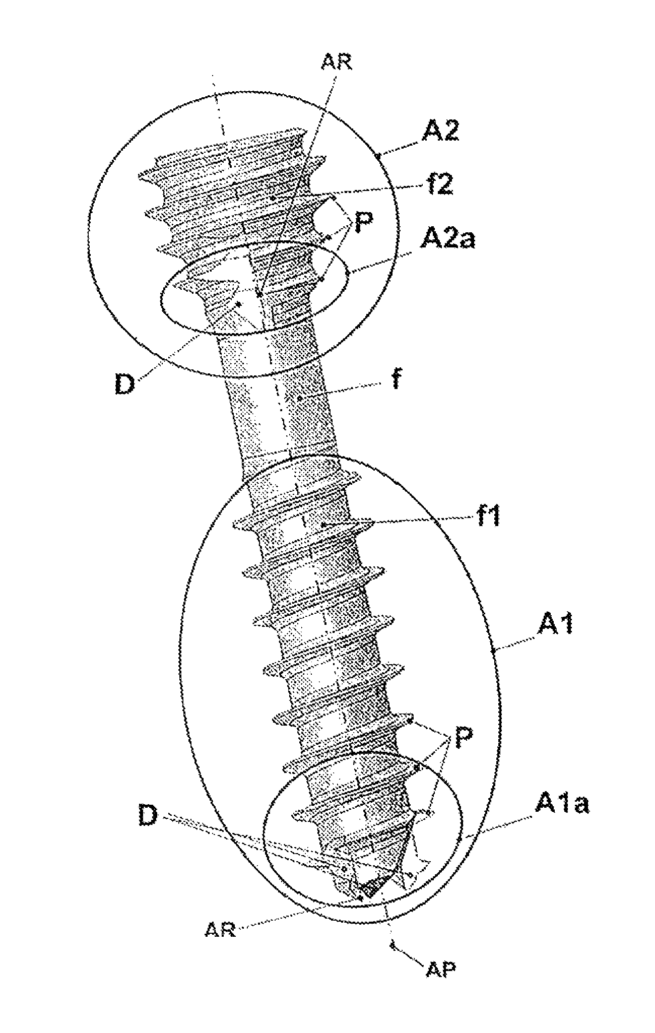
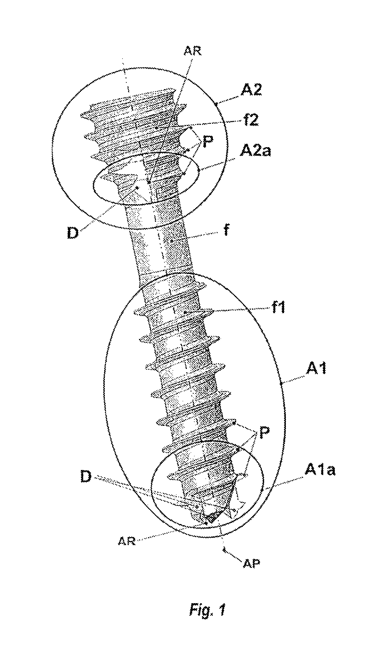
[0052]FIG. 1 shows a general view of the screw according to the embodiment of the invention most particularly described here, which shows two anchoring zones, namely a distal portion A1 and a proximal portion A2. The core formed with the screwthread, also called the barrel f, is generally cylindrical. For consistency, f1 is the portion of the barrel of the zone A1 at the distal end A1, that is to say the body of the screw except for the threads, and f2 is the portion of the barrel of the zone A2 at the proximal end A2. Each zone A1 and A2 has threads P and forms an attack zone (the first to come into contact with the bone and to bite into it when screwing in) A1a at the distal end, and A2a at the proximal end followed by a screwing zone.

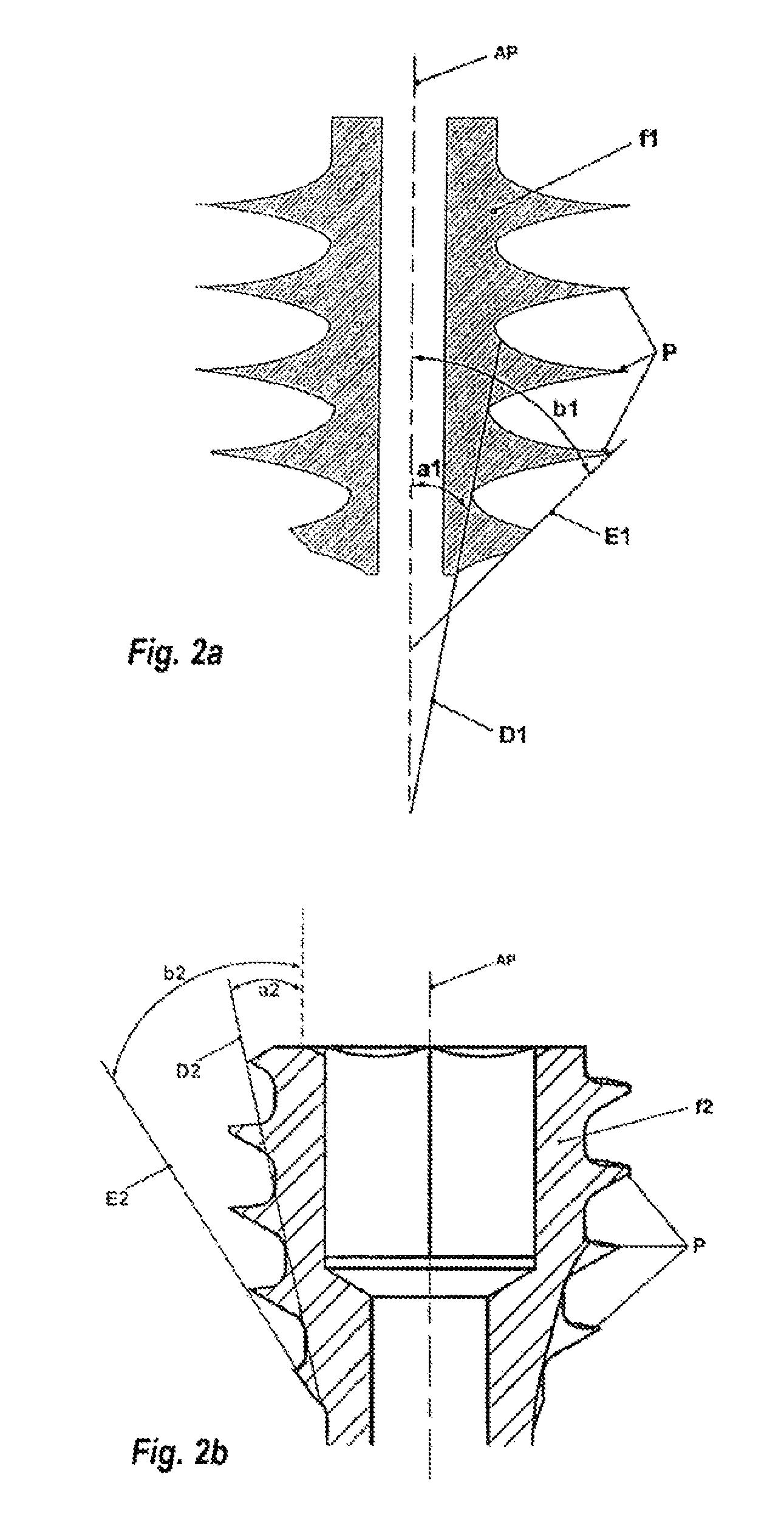
[0053]The distal and proximal attack zones Ala and A2a each comprise several teeth D, for example three teeth each defining a cutting ridge AR. These teeth D are formed by a notch or cut parallel to a main axis AP of the screw in order to create a cu...


PUM


Abstract

The invention relates to a self-tapping and self-boring osteosynthesis screw for compressive orthopaedic surgery, characterised in that, in the bone engagement regions, at both the distal portion (A1a) and at the proximal portion (A2a), the sum of the angles defining the outer taper of the shank (f) and the taper of the crest line of the screw thread pitch (P) is higher than 45°, and in that the leading portion (i.e. the most distal one) of each thread includes a plurality of cutting edges (AR) obtained by stock removal.

Description

CROSS-REFERENCE TO RELATED APPLICATIONS[0001]The present application is a continuation of U.S. patent application Ser. No. 13 / 146,925, filed Sep. 6, 2011, which application is a national phase entry under 35 U.S.C. §371 of International Application No. PCT / FR2010 / 000094, filed Feb. 9, 2010, published as International Publication No. WO 2010 / 089481 A1, which claims priority from French Patent Application No. 09 00557, filed Feb. 9, 2009, the disclosures of which are incorporated herein by reference.BACKGROUND OF THE INVENTION[0002]The invention relates to a screw for osteosynthesis and arthrodesis for orthopedic surgery.[0003]It finds a particularly important, although not exclusive, application in the field of anchors for orthopedic surgery of the hand and of the foot, more particularly at the phalanxes of the fingers and of the toes, but also of the metacarpals and metatarsals and notably for corrective surgery for the hand and for the foot.[0004]Note than an osteosynthesis anchor ...

Claims


Application Information

Patent Timeline
Patent Type & Authority Patents(United States)
IPC IPC(8): A61B17/58A61B17/86
CPCA61B17/863A61B17/8635A61B17/864
Inventor PRANDI, BERNARDLARIVIERE, JEANR'TAIMATE, MOHAMMED
Owner STRYKER EURO OPERATIONS HLDG LLC
Why Eureka
Try Eureka