Surgical biopsy system with control unit for selecting an operational mode
What is AI technical title?
AI technical title is built by Patsnap AI team. It summarizes the technical point description of the patent document.
a surgical biopsy and control unit technology, applied in the field of remote control surgical instruments, can solve the problems of limited application, high undesirable effects, and the need for the operator to move back
Inactive Publication Date: 2011-03-29
DEVICOR MEDICAL PROD
View PDF62 Cites 232 Cited by
Summary
Abstract
Description
Claims
Application Information
AI Technical Summary
This helps you quickly interpret patents by identifying the three key elements:
Problems solved by technology
Method used
Benefits of technology
Problems solved by technology
The aspiration method is less intrusive than most other sampling techniques, however, it has limited application since the structure of tissue excised by aspiration is destroyed, leaving only individual cells for analysis.
A common problem encountered by operators when using some types of automatic, powered surgical devices is the need for the operator to move back and forth between the patient and a control unit physically separated from the patient.
It is highly undesirable at this point for the operator to free one hand and to reach over to the control unit to actuate a control in order to select and enable the Sampling Mode of operation.
Neither Ritchart nor Bird, however, disclose a control adapted for remotely selecting and / or enabling an operational mode from a menu shown on a display without leaving the surgical field.
Method used
Image
Click on the blue label to locate the original text in one second.
Reading with bidirectional positioning of images and text.
Examples
Embodiment Construction
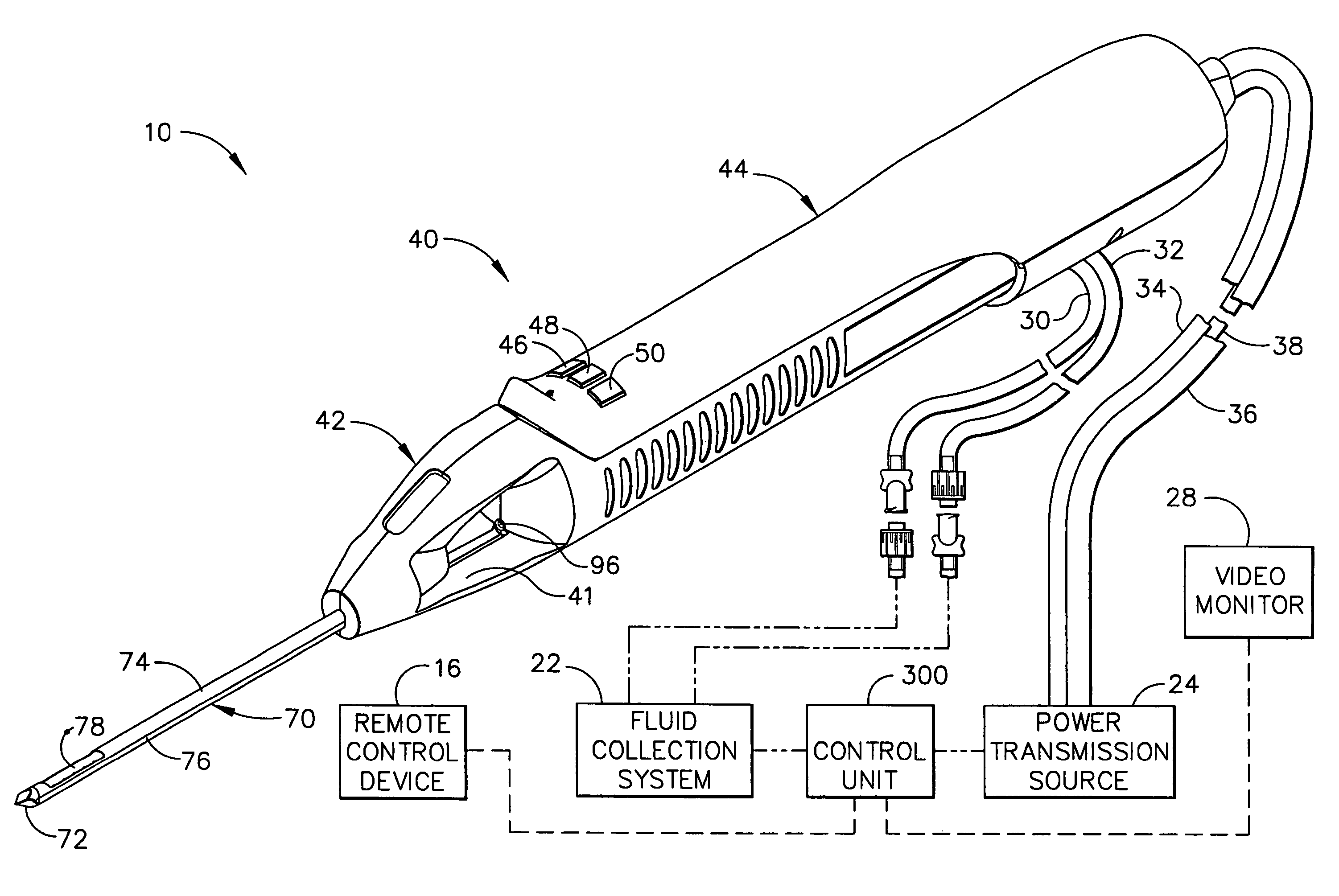
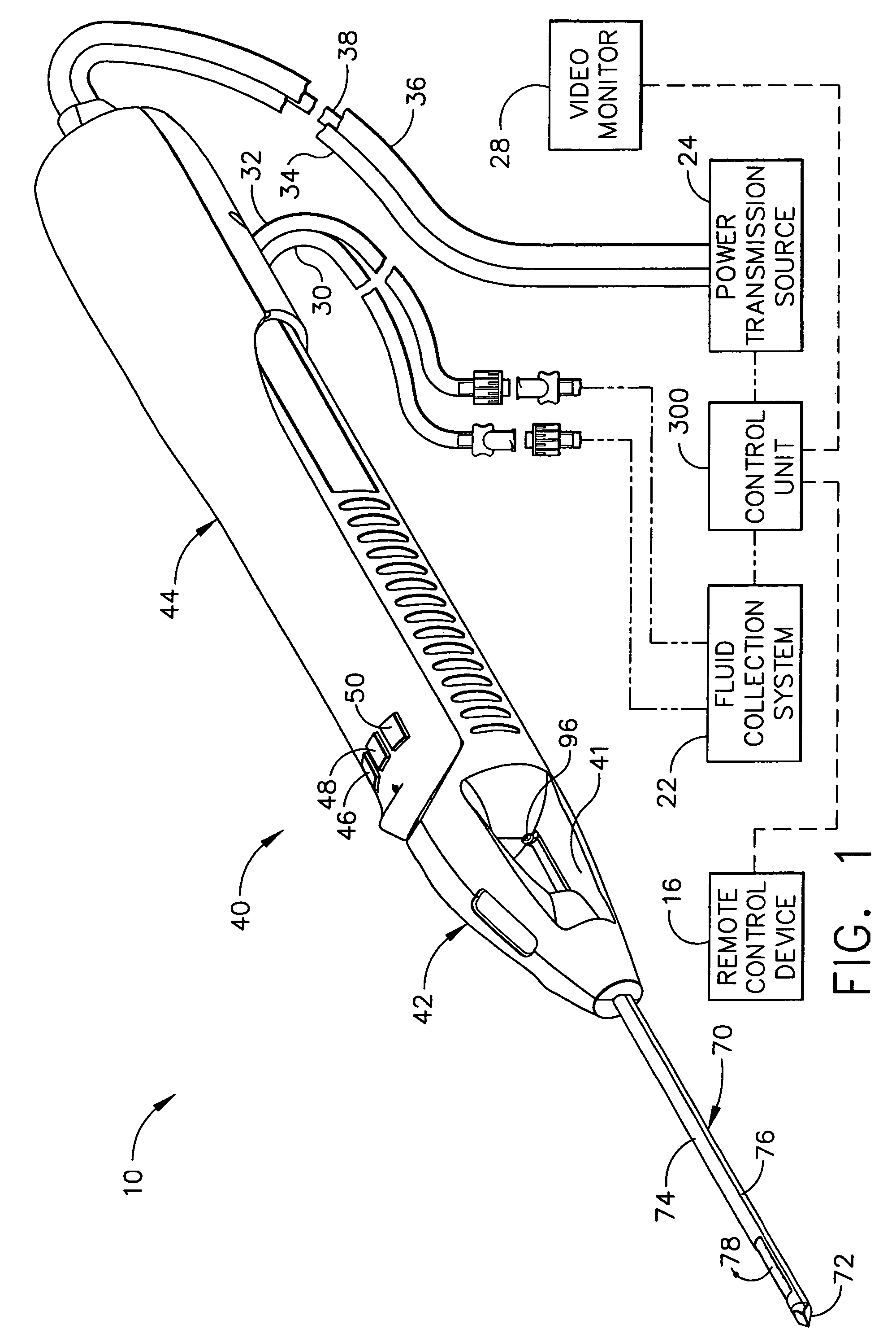
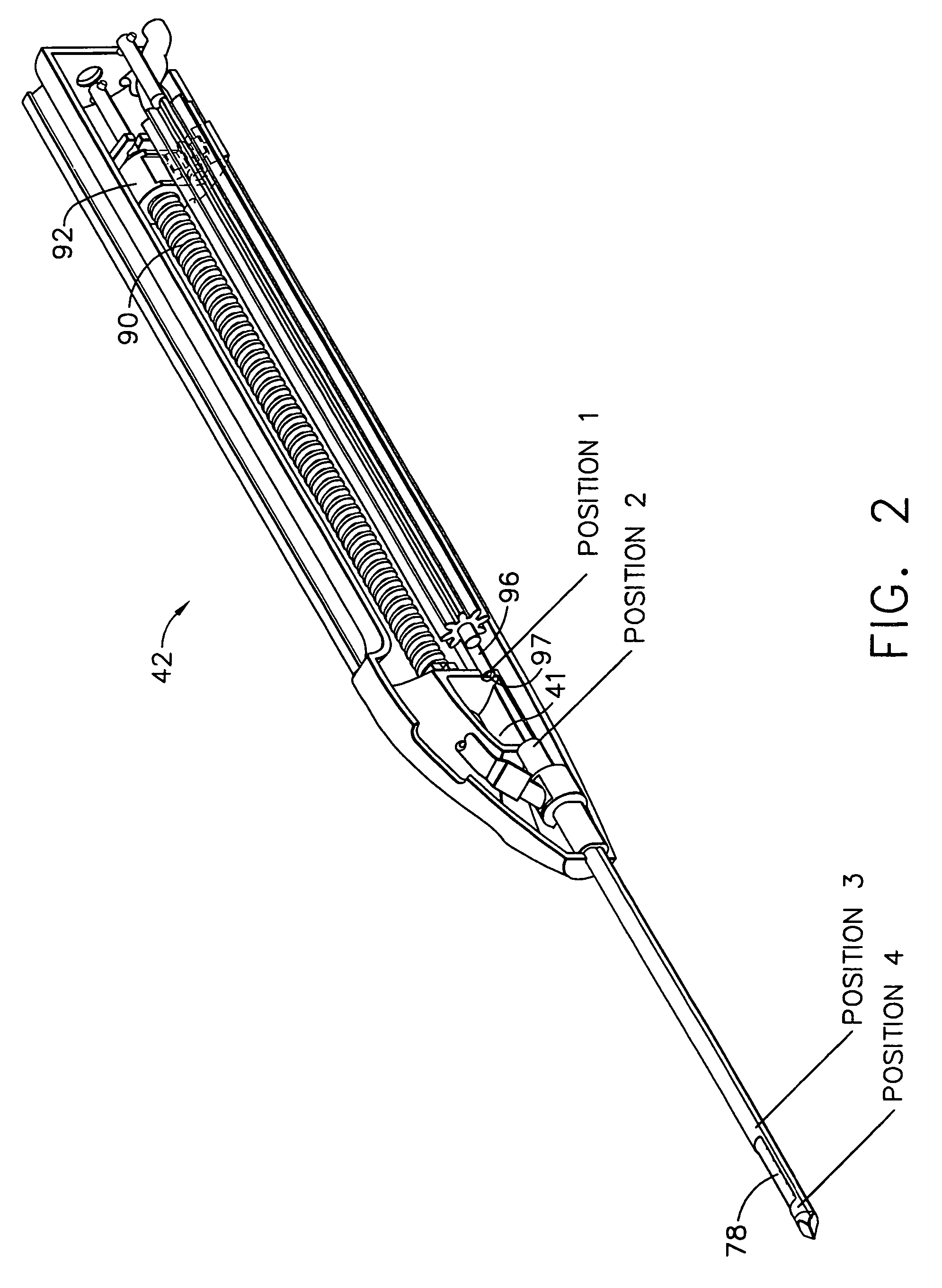
[0029]FIG. 1 shows a surgical biopsy system 10 comprising a handpiece 40, a fluid collection system 22, a control unit 300, a power transmission source 24, a video monitor 28 and a remote control 16. Detailed descriptions of surgical biopsy system 10 are contained in U.S. Patent Ser. No. 09 / 282,140 filed Mar. 31, 1999, which is hereby incorporated herein by reference. Handpiece 40 comprises a holster 44 operatively and removeably attached to a probe assembly 42. Handpiece 40 is lightweight, ergonomically shaped, and hand manipulatable. Probe assembly 42 includes an elongated piercer 70 having a piercer tip 72 for penetrating soft tissue of a surgical patient. Piercer 70 comprises a piercer tube 74 and a vacuum chamber tube 76. Vacuum chamber tube 76 of piercer 70 may be fluidly connected, automatically or manually, to fluid collection system 22 by a lateral vacuum line 30. Similarly, axial vacuum line 32 may be fluidly connected, automatically or manually, to fluid collection system...
PUM
Abstract
A surgical biopsy system is provided for removing at least one tissue sample from a surgical patient. The surgical biopsy system comprises an elongated, hollow piercer and a cutter rotatably and axially positionable relative to the piercer. The piercer has a lateral port for receiving the tissue sample into the piercer. The surgical biopsy system further comprises a power transmission source operatively connected to the cutter for rotating and translating the cutter, a control unit, and a display mounted in a display frame for showing an operator a plurality of operational modes of the surgical biopsy system. The surgical biopsy system further comprises at least one control button operatively connected to the control unit by a circuit and remotely located from the control unit. The operator may actuate the control button(s) to select any one of the operational modes and the selected operational mode is visually identifiable on the display.
Description
[0001]This divisional application claims priority to U.S. patent application Ser. No. 10 / 174,032 filed Jun. 18, 2002, now U.S. Pat. No. 6,752,768, which claims priority to U.S. patent application Ser. No. 09 / 466,491 filed Dec. 17, 1999 (now U.S. Pat. No. 6,428,487).[0002]This application is related to the following co-pending U.S. patent applications: Ser. No. 09 / 178,075, filed on Oct. 23, 1998; Ser. No. 09 / 282,142, filed on Mar. 31, 1999; Ser. No. 09 / 282,140, filed on Mar. 31, 1999; and Ser. No. 09 / 365,619, filed on Aug. 2, 1999. This application is further related to co-pending U.S. patent application Ser. No. 09 / 466,391 filed concurrently herewith on which is hereby incorporated by reference.FIELD OF THE INVENTION[0003]The present invention relates, in general, to remotely controlled surgical instruments, and more particularly, to a remotely controlled, surgical biopsy instrument including an apparatus for remotely selecting a particular mode of operation.BACKGROUND OF THE INVENT...
Claims
Application Information
Patent Timeline
Application Date:The date an application was filed.
Publication Date:The date a patent or application was officially published.
First Publication Date:The earliest publication date of a patent with the same application number.
Issue Date:Publication date of the patent grant document.
PCT Entry Date:The Entry date of PCT National Phase.
Estimated Expiry Date:The statutory expiry date of a patent right according to the Patent Law, and it is the longest term of protection that the patent right can achieve without the termination of the patent right due to other reasons(Term extension factor has been taken into account ).
Invalid Date:Actual expiry date is based on effective date or publication date of legal transaction data of invalid patent.

