Surgical stapling instrument with apparatus for providing anvil position feedback

a technology of anvil position feedback and surgical stapler, which is applied in the field of surgical staplers, can solve the problems of difficult for surgeons to effectively view the area of the colon being cut and stapled, inability to provide the desired amount of illumination to the area of the instrument, and laborious and time-consuming surgical procedures

Active Publication Date: 2011-04-05
CILAG GMBH INT
View PDF394 Cites 1766 Cited by
  • Summary
  • Abstract
  • Description
  • Claims
  • Application Information

AI Technical Summary

Benefits of technology

[0012]In accordance with another general form of the present invention, there is provided a surgical stapling instrument for applying one or more surgical staples to tissue. Various embodiments comprise a handle assembly and a shaft assembly that is coupled to the handle assembly. A stapling head assembly may be operably coupled to the shaft assembly. The stapling head assembly may comprise a staple cartridge for supporting one or more surgical staples, a staple driver for engaging and driving the staples from the staple cartridge. A knife may be movably supported in the stapling head assembly. A drive system may be provided for applying drive motions to the staple driver and the knife. The instrument may further include a source of electrical current. An indicator may also be provided on the instrument. The indicator may communicate with the source of electrical current. A trocar assembly may be movably supported by the shaft assembly and be configured to detachably support an anvil thereon. The trocar assembly may have a plurality of contact regions that communicate with the source of electrical current and the indicator. At least some of the contact regions may be electrically insulated from the first contact region such that when the anvil is attached to the distal end of the trocar assembly, the anvil electrically connects the first and second contact regions to permit the electrical current to flow to the indicator.

Problems solved by technology

Previously, this surgical procedure was a laborious and time consuming operation.
During the aforementioned stapling process, it is often difficult for the surgeon to effectively view the area of the colon being cut and stapled.
However, due to the limited amount of space available to maneuver and position such instrument within the colon, such instruments may not supply a desired amount of illumination to the area.
For example, in a lower anterior resection, it is often difficult for the surgeon to know if they have successfully attached the anvil to the trocar.
Also during the above-described surgical procedures, it is often difficult for the surgeon to know when the anvil has been moved to the desired closed position wherein it is ready to be fired.

Method used


Image

  • Surgical stapling instrument with apparatus for providing anvil position feedback
  • Surgical stapling instrument with apparatus for providing anvil position feedback
  • Surgical stapling instrument with apparatus for providing anvil position feedback

Examples


Embodiment Construction

[0029]Certain exemplary embodiments will now be described to provide an overall understanding of the principles of the structure, function, manufacture, and use of the devices and methods disclosed herein. One or more examples of these embodiments are illustrated in the accompanying drawings. Those of ordinary skill in the art will understand that the devices and methods specifically described herein and illustrated in the accompanying drawings are non-limiting exemplary embodiments and that the scope of the various embodiments of the present invention is defined solely by the claims. The features illustrated or described in connection with one exemplary embodiment may be combined with the features of other embodiments. Such modifications and variations are intended to be included within the scope of the present invention.

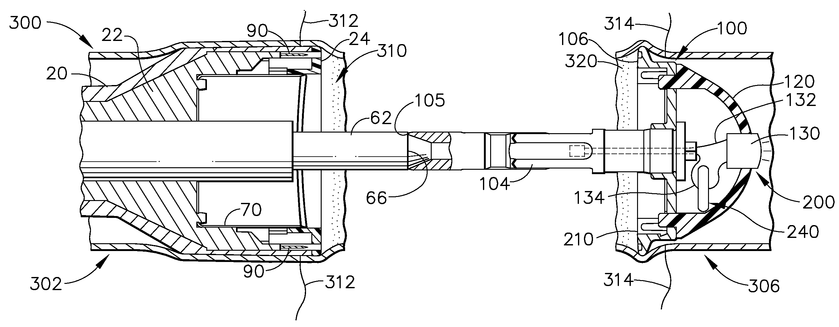
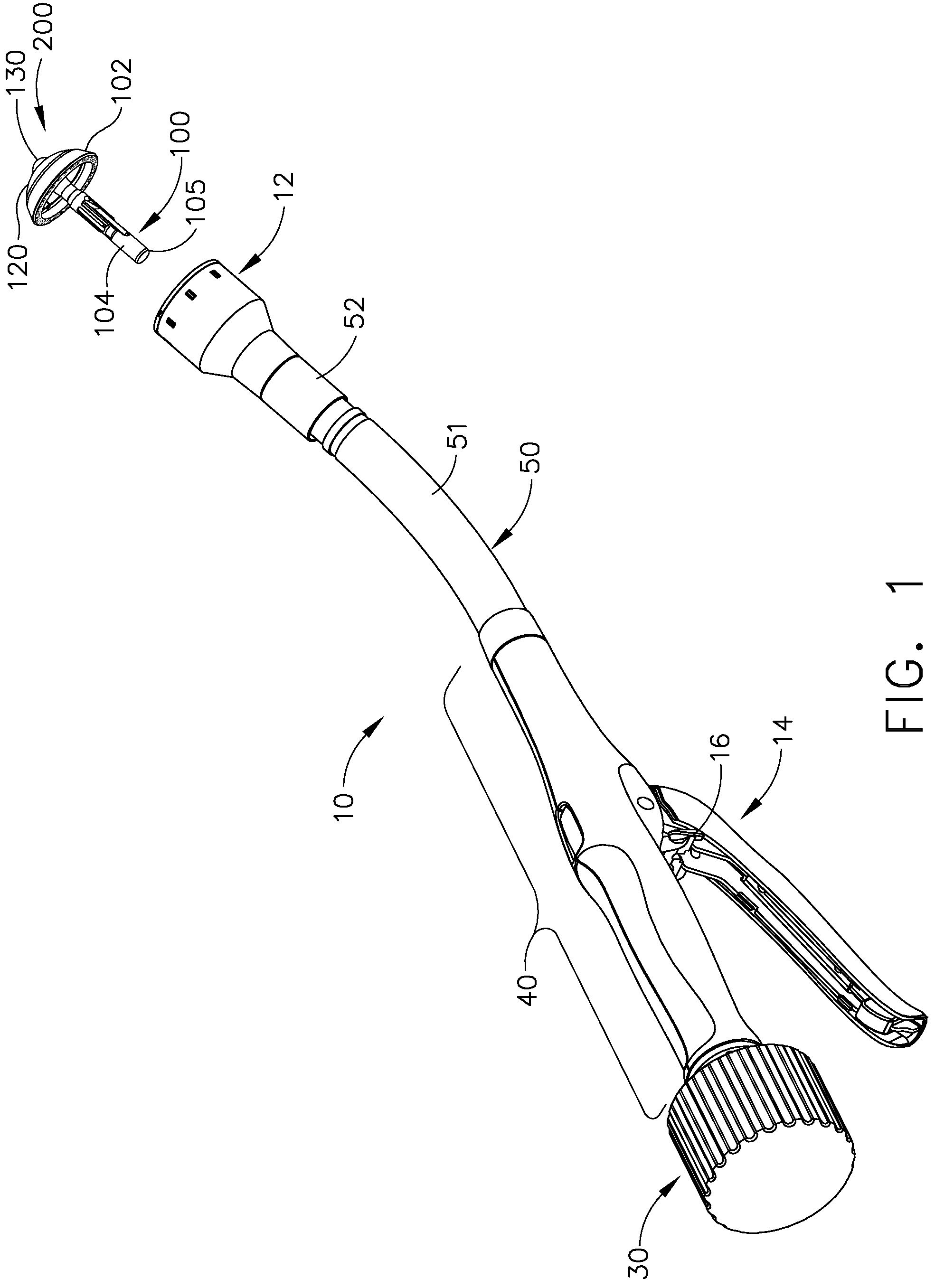
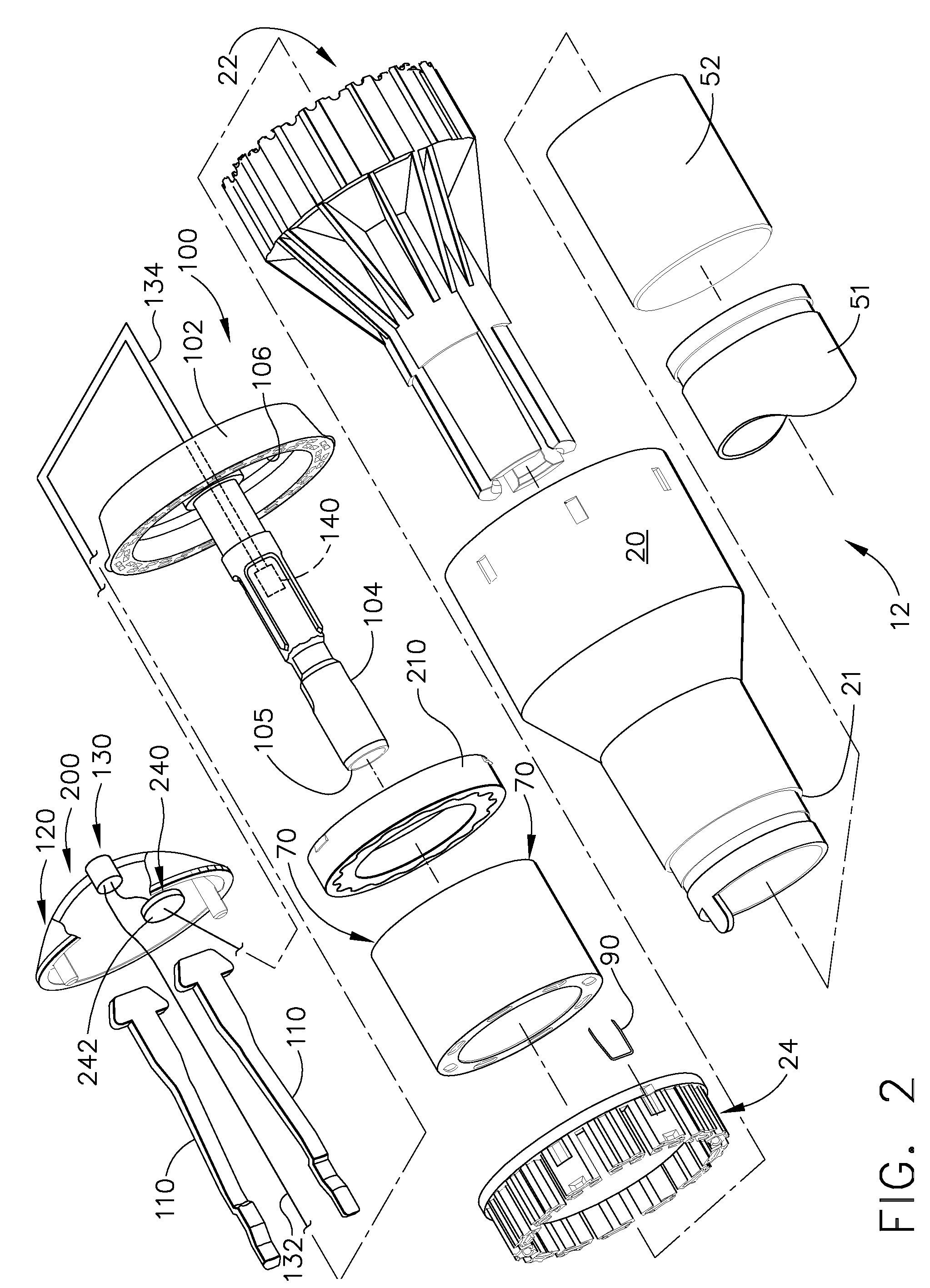
[0030]Turning to the Drawings, wherein like numerals denote like components, there is shown a circular stapler 10 that includes a unique and novel system for provi...


PUM

PropertyMeasurementUnit
electrical currentaaaaaaaaaa
electrical current flowaaaaaaaaaa
timeaaaaaaaaaa

Abstract

Circular stapling instruments for cutting and applying one or more surgical staples to tissue are disclosed. The instruments include various forms of feedback systems designed to provide at least one mode of feedback to the surgeon when the anvil has been attached to the device and / or when the anvil has been attached to the device and oriented in a firing position. Various types of feedback indicators are disclosed such as illumination devices, sound generating devices and vibration generation devices. In various embodiments, the feedback indicator comprises at least one illumination device mounted on the anvil which indicates that the anvil has been properly attached to the instrument and which can also serve to illuminate the surgical site.

Description

FIELD OF THE INVENTION[0001]The present invention generally relates to surgical staplers, and more particularly, to circular stapling instruments for performing anastomosis stapling operations.BACKGROUND[0002]In certain types of surgical procedures, the use of surgical staples has become the preferred method of joining tissue and, as such, specially configured surgical staplers have been developed for these applications. For example, intra-luminal or circular staplers have been developed for use in a surgical procedure known as an anastomosis. Circular staplers useful for performing an anastomosis are disclosed, for example, in U.S. Pat. Nos. 5,104,025; 5,205,459; 5,285,945; and 5,309,927 which are each herein incorporated by reference in their respective entireties.[0003]One form of an anastomosis comprises a surgical procedure wherein sections of intestine are joined together after a diseased portion has been excised. The procedure requires re-joining the ends of the two tubular s...

Claims


Application Information

Patent Timeline
Patent Type & Authority Patents(United States)
IPC IPC(8): A61B17/068
CPCA61B17/1114A61B17/115A61B2019/4857A61B2017/07257A61B2017/00128A61B2090/0811A61B17/1155
Inventor MEASAMER, JOHN P.SHELTON, IV, FREDERICK E.BAXTER, III, CHESTER O.FUCHS, RICHARD P.MOLITOR, NICHOLAS G.THOMPSON, BENNIETSONTON, MARK
Owner CILAG GMBH INT
Why Eureka
Try Eureka