Magnetic flowmeter with coil ground path detection

a magnetic flowmeter and coil ground technology, applied in the field of magnetic flowmeters, can solve the problems of the inability to detect the coil ground path,

Active Publication Date: 2011-04-12
MICRO MOTION INC
View PDF15 Cites 20 Cited by
  • Summary
  • Abstract
  • Description
  • Claims
  • Application Information

AI Technical Summary

Problems solved by technology

The coils in the magnetic flowmeter flowtube may be compromised by process fluid leaking into the coil compartment.
This can cause an electrical path between the coil and electrical ground.
This will lead to inaccurate flow measurements.
The loss of the coil drive signal typically cannot be detected by simply measuring the coil drive current.

Method used


Image

  • Magnetic flowmeter with coil ground path detection
  • Magnetic flowmeter with coil ground path detection
  • Magnetic flowmeter with coil ground path detection

Examples


Embodiment Construction

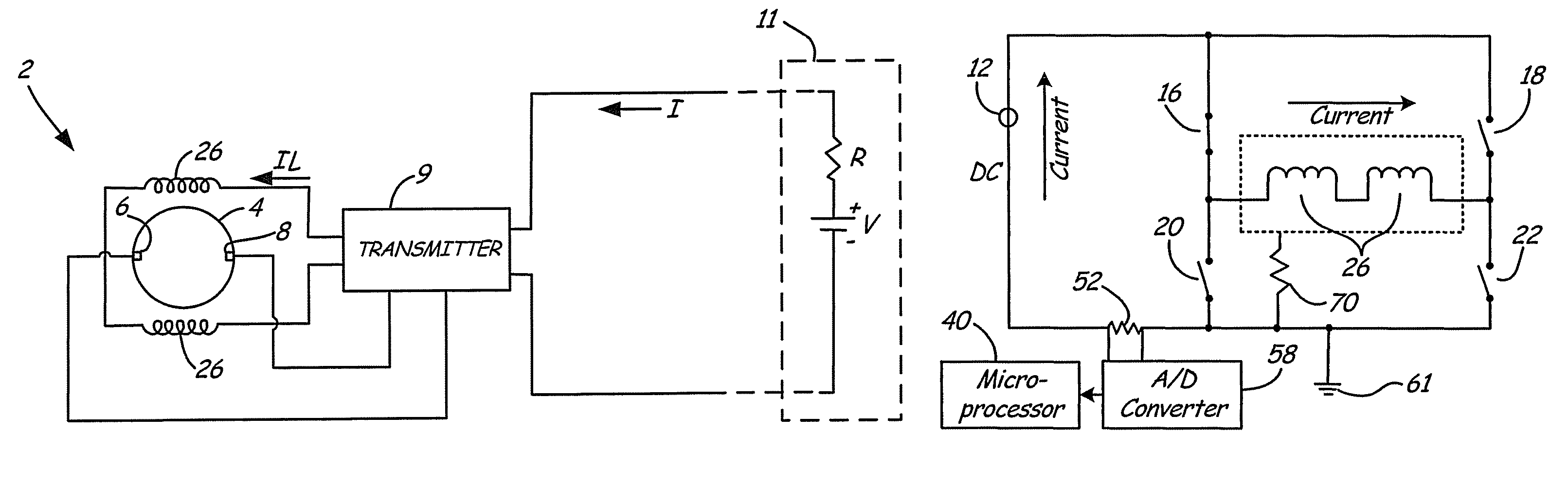
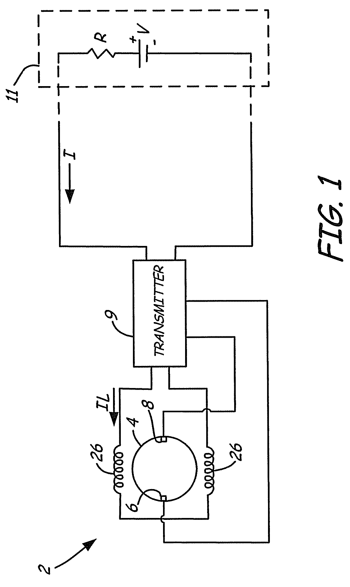
[0012]In FIG. 1, magnetic flowmeter system 2 connects to two-wire communication 4-20 mA loop carrying current I and an AC power line (not shown). Flowtube 4 carries a fluid flow. Transmitter 9 supplies coil drive current IL to coils 26 adjacent flowtube 4 which generate a magnetic field in the fluid. Electrodes 6,8 mount in flowtube 4 along a line perpendicular to the magnetic field in the fluid for sensing EMF induced by the fluid flow. Transmitter 9 senses the EMF between electrodes 6,8 and controls a DC output current I representative of the sensed EMF which is, in turn, proportional to fluid flow. Transmitter 9 transmits current I over a 4-20 mA current loop to a remote receiving station 11. Transmitter 9 can also transmit the flow output digitally using HART digital protocol, a Fieldbus protocol, a wireless protocol, or other technique.

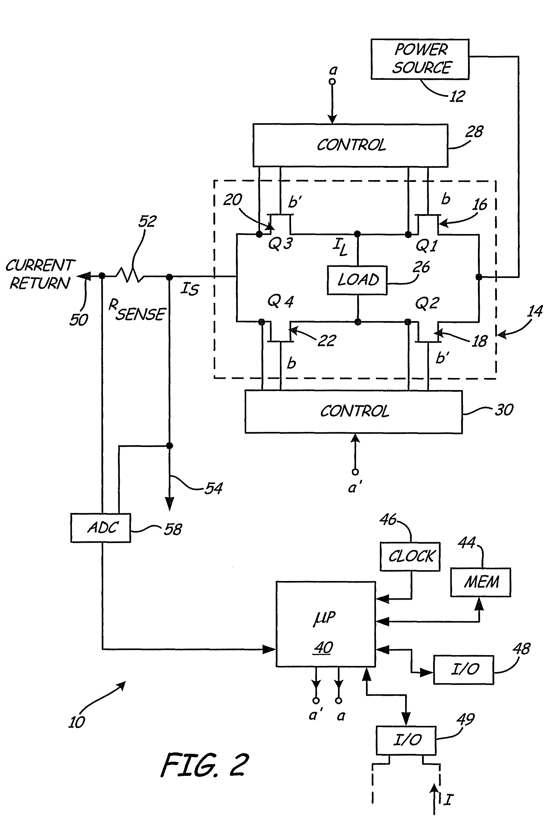
[0013]FIG. 2 shows driver circuitry 10 in transmitter 9. H-bridge flowtube driver 10 of magnetic flowmeter system 2 generates alternating drive ...


PUM


Abstract

A magnetic flow meter includes a flowtube arranged to receive a flow of process fluid and a coil proximate the flowtube arranged to apply a magnetic field to the process fluid. A sense electrode is arranged to sense a voltage potential in the flowtube in response to the applied magnetic field. The sensed voltage is indicative of flow rate of process fluid through the flowtube. Diagnostic circuitry provides an output related to an electrical path between the coil and electrical ground.

Description

BACKGROUND OF THE INVENTION[0001]The present invention relates to magnetic flowmeters. More specifically, the present invention relates to magnetic flow meters with coil ground path detection.[0002]A magnetic flowmeter measures the volumetric flow rate of a conductive fluid by detecting the velocity of the fluid passing through a magnetic field. Magnetic flowmeter systems typically include a flowtube assembly and a transmitter assembly. The flowtube assembly is installed in a process piping line, either vertically or horizontally, and includes a pipe section, a coil section and electrodes. The coils are located on opposite sides of a cross section of the pipe. The coils, energized by a coil drive current from the transmitter, develop a magnetic field along the cross section of the pipe. Two electrodes are located across the pipe from each other along a line which is perpendicular to the magnetic field. Fluid passing through the pipe is electrically conductive. As a result of the con...

Claims


Application Information

Patent Timeline
Patent Type & Authority Patents(United States)
IPC IPC(8): G01F1/58
CPCG01F25/0007G01F1/586G01F25/10
Inventor FOSS, SCOT R.SCHULZ, ROBERT K.
Owner MICRO MOTION INC
Why Eureka
Try Eureka