Device for cutting the cornea of an eye

a technology for cutting the cornea and the eye, which is applied in the field of eye surgery and eye treatment, can solve the problems of blades being particularly sensitive to shear stress, unable to penetrate the elastic and extremely tough outer layer of the eye, and unable to meet the needs of patients,

Inactive Publication Date: 2011-04-12
DAXER ALBERT
View PDF22 Cites 6 Cited by
  • Summary
  • Abstract
  • Description
  • Claims
  • Application Information

AI Technical Summary

Benefits of technology

[0008]The underlying objective of the present invention therefore is to design a device for cutting the cornea of an eye to correct its refractive power on the basis of the state-of-the-art technique initially described in such a way that, departing from the very point at which the tip of the blade is placed on the cornea, a pocket lying in the cutting plane of the blade may be cut via a tunnel-like entry, without any impairment of the stability of the cornea to be expected. In addition, the device shall be aimed at allowing a broad range of refractive power corrections.

Problems solved by technology

That is to say, it is relatively difficult to penetrate the elastic and extremely tough outer layer of the cornea.
Moreover, the blade must not get deformed during cutting as in that case an exact cutting plane and preventing perforation of the outer or inner layer of the cornea may not be guaranteed, whereby the successful correction of the refractive power would be precluded.
While this eventuality may be counteracted by using blades of greater hardness (e.g. made of diamond material), such blades are particularly sensitive to shear stress, which excludes the use of said blades in the device according to US 2001 / 0004702, given the fact that the blade rests on the frame.
Moreover, such blades bear the risk of breakage and also their sharpness would be greatly impaired.
This method has the disadvantage that, as already noted, the stability of the cornea is greatly impaired, which may occasionally result in undesirable bulges of the corneal surface.

Method used


Image

  • Device for cutting the cornea of an eye
  • Device for cutting the cornea of an eye
  • Device for cutting the cornea of an eye

Examples


Embodiment Construction

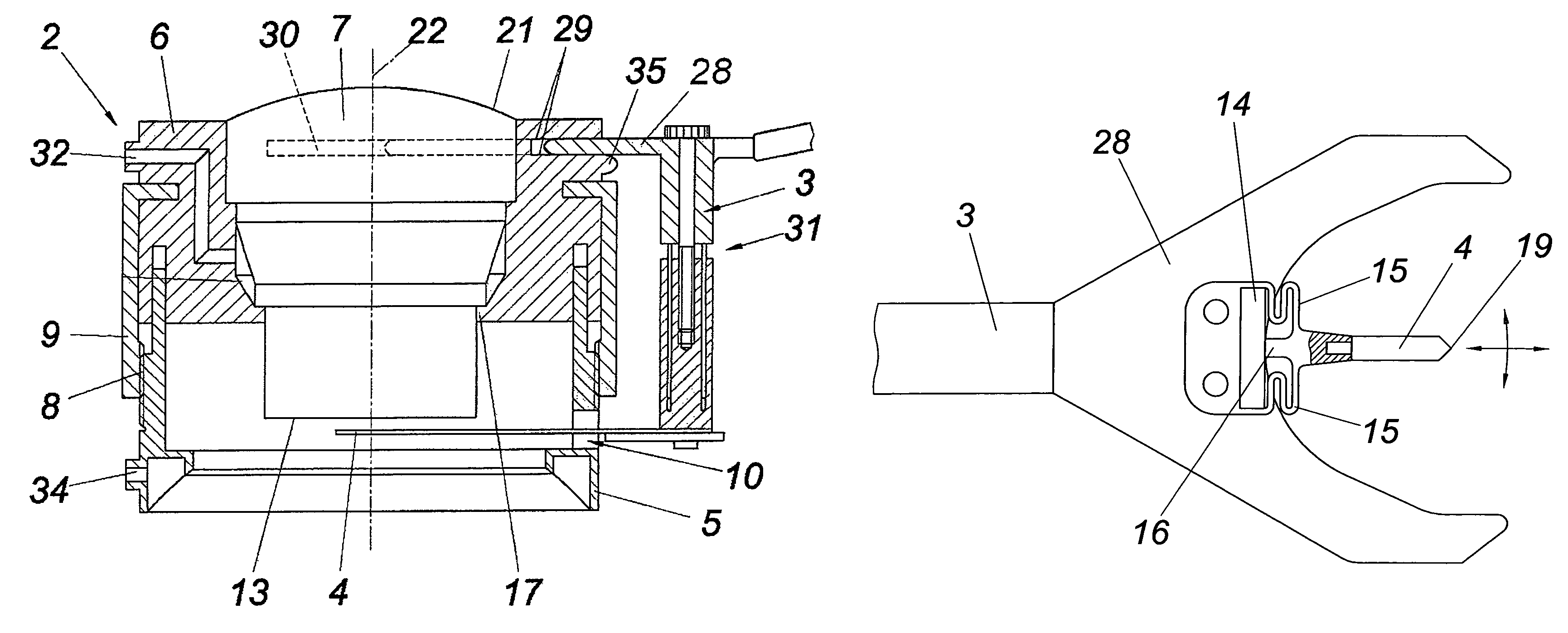
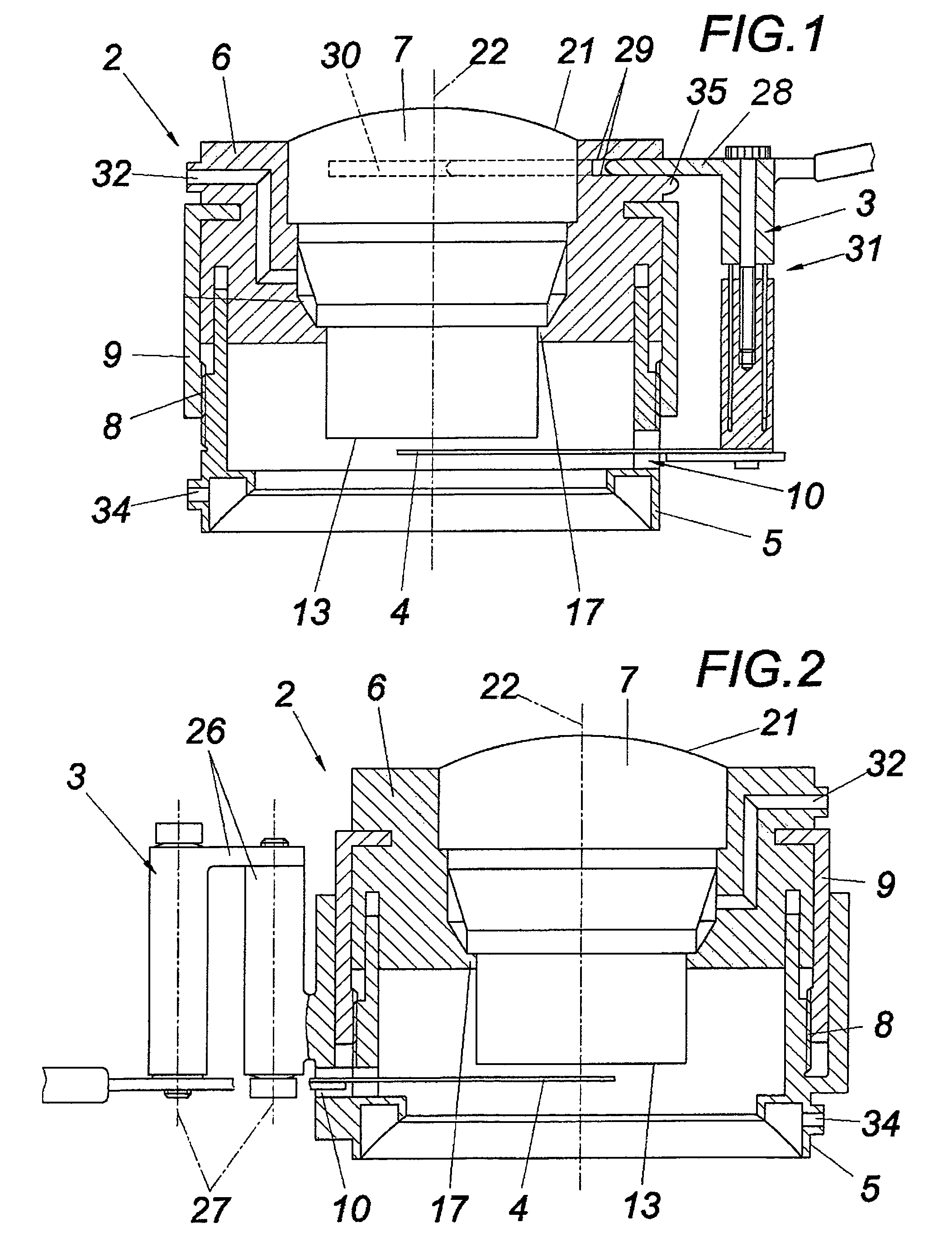
[0035]Pursuant to the exemplary embodiment in FIG. 1 and the exemplary embodiment in FIG. 2, the devices for cutting a cornea 1 of an eye to correct its refractive power according to the invention generally comprise a frame 2 and a holding device 3 for supporting a blade 4. The frame 2 has a fixation ring 5, which may be drawn onto the eye, and a receptacle 6, which may be coaxially displaced relative to the fixation ring 5 and which serves to accommodate an applanator 7 for deforming the cornea within the fixation ring 5. The cornea 1 thus projects through the fixation ring 5, within which, in particular offset in height relative to the fixation ring 5, the applanator 7 for impingement of the cornea is located. The fixation ring 5 is furnished with a thread 8 for coaxial displacement, in which a nut 9 engages that is mounted on the receptacle 6 allowing rotation.

[0036]By rotating the nut 9, the receptacle 6 and / or the applanator 7 may thus be displaced relative to the fixation ring...


PUM


Abstract

The invention relates to a device for cutting the cornea of an eye to correct the refractive power thereof, having a frame that comprises a fixation ring, which may be drawn onto the eye, as well as a receptacle, which may be coaxially displaced relative to the fixation ring and which serves to accommodate an applanator for deforming the cornea within the fixation ring, and a holding device, which is guided on the frame in a plane that is perpendicular to the axis with regard to the fixation ring and which serves to hold a blade, which passes through the frame via a peripheral recess and which is mounted in front of the applanator, being radially displaceable relative to the fixation ring as well as movable around an axis perpendicular to the guiding plane, for the purpose of cutting a pocket through a merely tunnel-like entry into the corneal tissue. In order to obtain advantageous cutting conditions, it is suggested to have the blade pass through the frame recess with clearance, and to have the holding device support a vibrator for setting the blade in oscillatory motion in the cutting plane.

Description

CROSS REFERENCE TO RELATED APPLICATIONS[0001]Applicant claims priority under 35 U.S.C. §119 of Austrian Patent Application Serial No. A663 / 2003 filed May 2, 2003, Austrian Patent Application Serial No. A840 / 2003 filed May 30, 2003, Austrian Patent Application Serial No. A1264 / 2003 filed Aug. 12, 2003 and Austrian Patent Application Serial No. A299 / 2004 filed Feb. 25, 2004. Applicant also claims priority under 35 U.S.C. §365 of PCT / AT2004 / 000147 filed Apr. 30, 2004. The international application under PCT article 21(2) was not published in English.[0002]1. Field of the Invention[0003]The invention relates to a device for cutting the cornea of an eye in order to correct the refractive power thereof, having a frame that comprises a fixation ring, which may be drawn onto the eye, as well as a receptacle, which may be coaxially displaced relative to the fixation ring and which serves to accommodate an applanator for deforming the cornea within the fixation ring, and a holding device, whi...

Claims


Application Information

Patent Timeline
Patent Type & Authority Patents(United States)
IPC IPC(8): A61F9/00A61F9/013
CPCA61F9/0133A61F9/013
Inventor DAXER, ALBERT
Owner DAXER ALBERT
Why Eureka
Try Eureka