Tool clamping insert and tool clamping device

a tool and insert technology, applied in the field of tool clamping inserts, can solve the problems of uncontrolled enlargement or expansion of the diameter of the centering, inaccuracy and stability loss, and dimensional changes, and achieve the effect of large clamping force and large torqu

Inactive Publication Date: 2007-02-22
ESA EPPINGER
View PDF7 Cites 3 Cited by
  • Summary
  • Abstract
  • Description
  • Claims
  • Application Information

AI Technical Summary

Benefits of technology

[0003] Clamping inserts are known, especially for applications in which ensuring a very precise clamping of a tool or drill bit or a boring bar is of concern, in which tools are clamped by their shank into a corresponding tool holder hole of a clamping insert body in shrink fit. As a rule, the tool holder hole is a straight cylindrical bore whose diameter when the tool shank has not been inserted is somewhat smaller than the diameter of the tool shank. To clamp the tool shank, the tool insert or a part thereof is inductively heated throughout using an induction coil so that the tool holder expends to a diameter that permits the tool shank to be inserted. In the subsequent cooling, the part of the clamping insert body surrounding the tool holder hole shrinks until the interior wall of the tool holder hole fits the shank of the tool and is clamped thereto in shrink fit. By appropriately dimensioning the diameter of the tool holder hole, it is thereby possible to achieve very large clamping forces which result in a correspondingly large torque being transferred from the tool clamping insert to the tool. This technique is known per se, a fact which also applies to the same extent to the achievable advantages.

Problems solved by technology

But tool clamping inserts of this type have the basic problem that the tool shank shrink-fitted into the tool holder hole brings about dimensional changes in the tool-carrier / tool-clamping-insert interface during the shrink-fit process, these changes in particular appearing as uncontrolled enlargements or expansions of the diameter of the centering pivot of the tool clamping insert.
The consequences of these changes are inaccuracies and stability losses in the region of the tool-carrier / tool-clamping-insert interface.

Method used


Image

  • Tool clamping insert and tool clamping device
  • Tool clamping insert and tool clamping device
  • Tool clamping insert and tool clamping device

Examples


Embodiment Construction

)

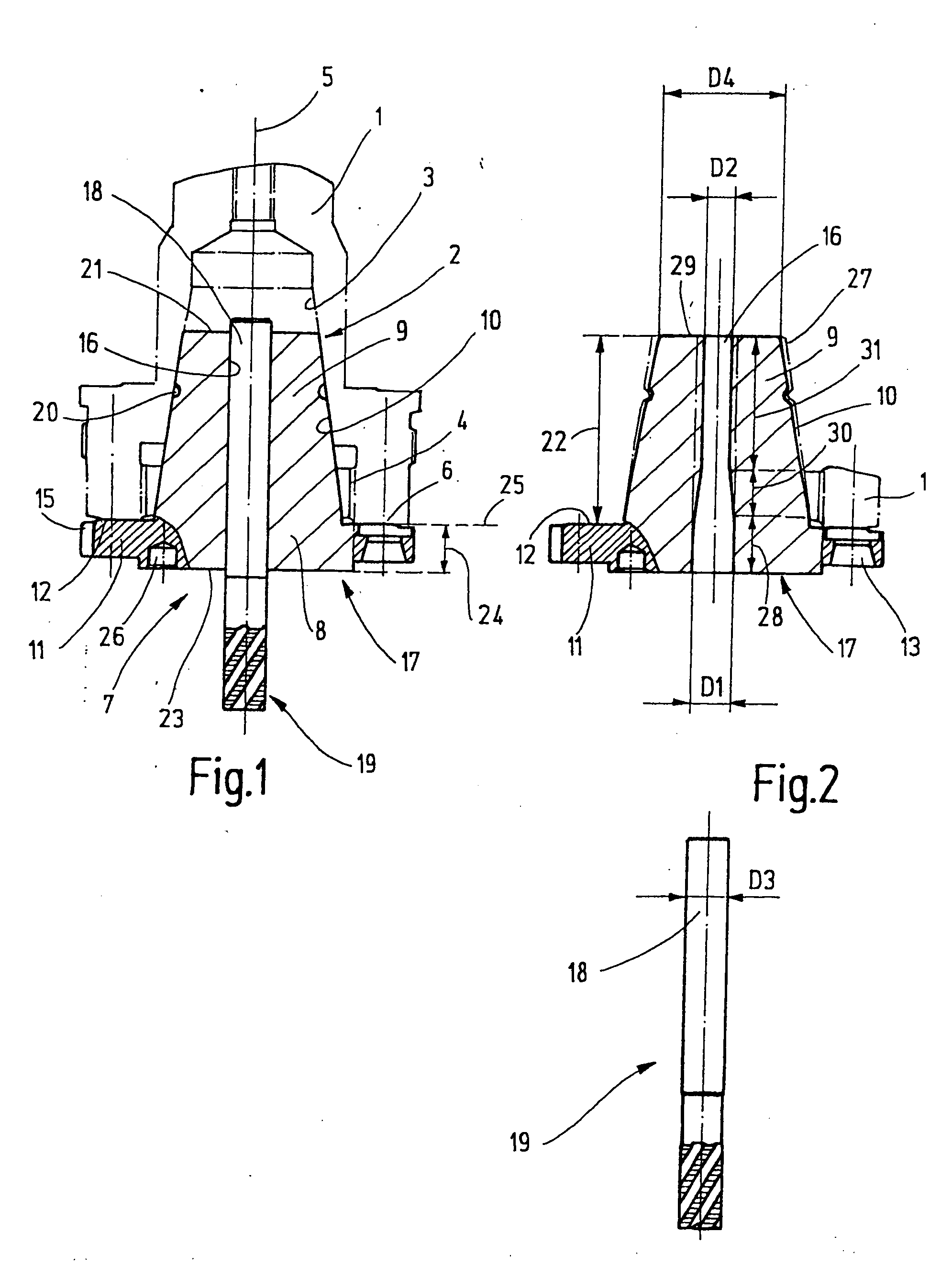
[0026] The tool clamping device for stationary and rotating tools illustrated in FIG. 1 demonstrates a tool carrier schematically indicated by 1, e.g. in the form of a work spindle only illustrated in cutout, which comprises a clamping-insert recess which, in the illustrated exemplary embodiment, is configured as collet-chuck recess 2 with a conical collet-chuck boring 3. Collet-chuck recesses and the associated collet chucks are standardized according to DIN 6499, April 2002, pages 1 to 8. A collet (not illustrated) can be clamped into the collet-chuck recess 2 by means of a collet nut, which is screwed into an inside thread 4, as is known per se. The collet-chuck recess 2 demonstrates an associated first flat surface 6, which is configured on the tool carrier 1 and runs perpendicular to the longitudinal center line 5 of the collet-chuck recess.

[0027] In the present case, the collet-chuck recess 2 serves for receiving a tool clamping insert 7, which demonstrates a clamping insert...


PUM

PropertyMeasurementUnit
diameter D3aaaaaaaaaa
axial lengthaaaaaaaaaa

Abstract

A tool clamping insert has a tool holder for receiving a tool shank. The tool holder hole is nominally smaller than the tool shank to be therein but upon heating of the insert expands to a size permitting insertion of the tool shank and, upon cooling, shrink fitting therein. The insert has an external clamping surface and is positioned in a clamping unit. The clamping surface and the tool holder hole are each configured with diameters, external and internal respectively, that change along the progression of their axial lengths.

Description

CROSS REFERENCE TO RELATED APPLICATION [0001] This application is based on German patent application no. 10 2005 038 582.6 filed Aug. 16, 2005. BACKGROUND OF THE INVENTION [0002] The invention relates to a tool clamping insert for stationary or rotating tools for use in a tool carrier comprising a tool clamping recess which demonstrates a narrowly tolerated internal clamping surface at least locally. In addition, the invention relates to a tool clamping device having such a tool clamping insert. SUMMARY OF THE INVENTION [0003] Clamping inserts are known, especially for applications in which ensuring a very precise clamping of a tool or drill bit or a boring bar is of concern, in which tools are clamped by their shank into a corresponding tool holder hole of a clamping insert body in shrink fit. As a rule, the tool holder hole is a straight cylindrical bore whose diameter when the tool shank has not been inserted is somewhat smaller than the diameter of the tool shank. To clamp the t...

Claims


Application Information

Patent Timeline
Patent Type & Authority Applications(United States)
IPC IPC(8): B23P19/04B23C3/00
CPCB23B31/1179B23P11/027H05B6/14H05B6/40Y10T409/30952Y10T29/53704Y10T29/49865Y10T279/17Y10T279/17965
Inventor NEUMEIER, MANFRED
Owner ESA EPPINGER
Why Eureka
Try Eureka